Electrical Construction Symbols vs. Schematic Symbols
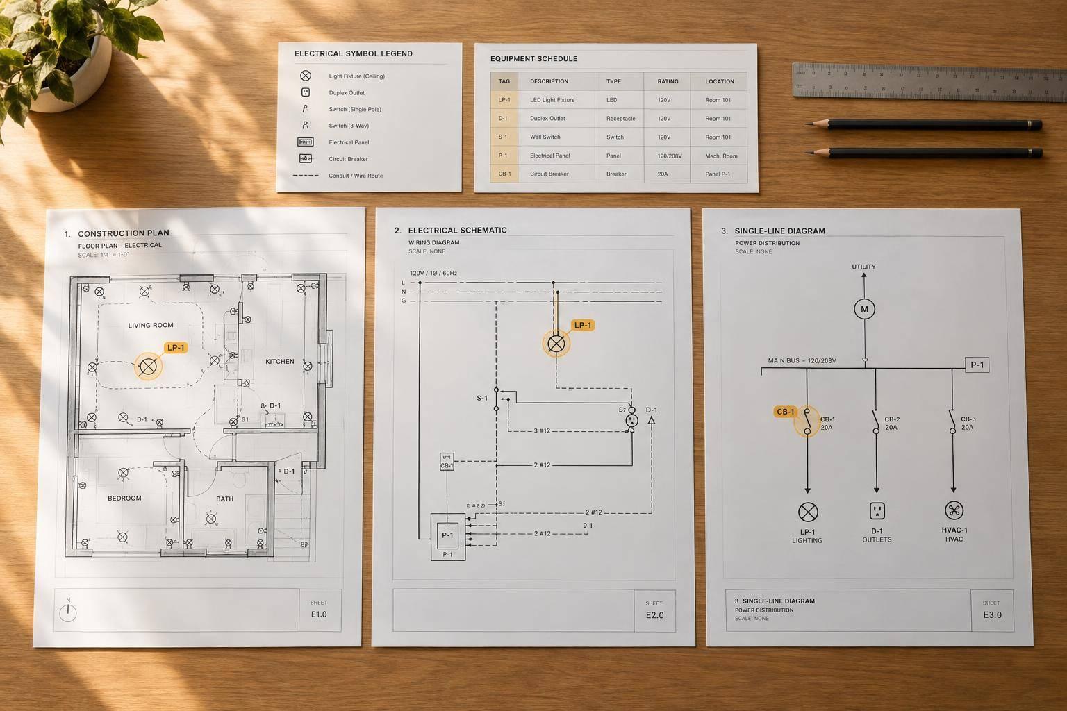
I start with the drawing type - not the symbol’s shape. Construction plans show where equipment goes, schematics show how circuits work, and single-line diagrams show how power reaches equipment.
Here’s my quick comparison:
| What I check | Construction plan | Schematic | Single-line diagram |
|---|---|---|---|
| Main purpose | Location and mounting | Circuit function and control logic | Power distribution and protection |
| Lines represent | Routes or circuit references, when shown | Functional connections | Simplified feeder connections |
| Supporting documents | Dimensions, details, schedules | Wiring diagrams, control sequences | Equipment ratings, feeder schedules, fault-current studies |
To follow one asset across all 3 drawing types, I check its tag and sheet references, then confirm the legend, schedules, and specifications. A connection line is not proof of a physical cable route.
My rule: <u>check the documents before making an assumption</u>. If tags, ratings, control states, or revisions conflict, I seek clarification. For more detailed walkthroughs, see our guides for bid & tender teams. The same review applies to generated drawings - they are not approved just because they look finished.
Construction Plans vs. Schematics vs. Single-Line Diagrams
Symbol Conventions by Drawing Type
Construction Symbols: Location and Installation
On plan views, treat symbols as installation instructions, not operating logic. They show location, device type, mounting, and circuit reference. For receptacles, switches, luminaires, and panels, check each graphic’s count, type, mounting height, circuit reference, tag, rating, and notes. A homerun arrow identifies the destination panel and circuit group without showing every conductor. Device locations are approximate unless dimensions, coordinates, grid references, elevations, or mounting details specify otherwise. These views don’t show internal logic or terminal wiring.
NECA 100 standardizes construction symbols; NFPA 70 governs installation requirements. Symbol groups cover luminaires, outlets and receptacles, switches and sensors, distribution equipment, communications, fire alarm, and related systems. Check whether device counts appear inside the symbol, beside it, or in the legend. The same tag appears in schematics and single-line diagrams, but with a different symbol.
Schematic Symbols: Components and Control Logic
Schematics move from installation details to control sequence. Follow the functional connections between contacts, relay coils, fuses, circuit breakers, motors, pilot lights, sensors, control transformers, and terminals. These connections explain sequence, interlocks, and control operation.
Read contacts in the stated reference condition - often de-energized, normal, or as shown. A coil and its associated contacts may appear separately, and spacing on the schematic doesn’t indicate physical location. Use the equipment tag to match the control logic to the device on the construction plan.
Single-Line Symbols: Distribution and Protection
Single-line diagrams focus on power distribution and protection, rather than control logic. One line represents power flow through services, generators, transformers, switchgear, switchboards, panelboards, transfer switches, motor control centers (MCCs), feeders, and major loads.
Check the annotations for voltage, phase, frequency, ratings, transformer ratio, conductor size, conductor count, bus rating, and equipment IDs. Compare the interrupting rating with the available fault current - ampere rating alone isn’t enough.
Unless specifically annotated, single-line diagrams may leave out neutral conductors, branch-circuit routing, control wiring, exact equipment placement, and many parallel conductors. Refer to the legend, schedules, specifications, layouts, and details for conductor, dimension, clearance, and routing data. Use equipment tags and reference notes to compare the same asset across all three views.
sbb-itb-f008923
Understanding Blueprints: Electrical Symbols Explained
Construction Plans vs. Schematics vs. Single-Line Diagrams
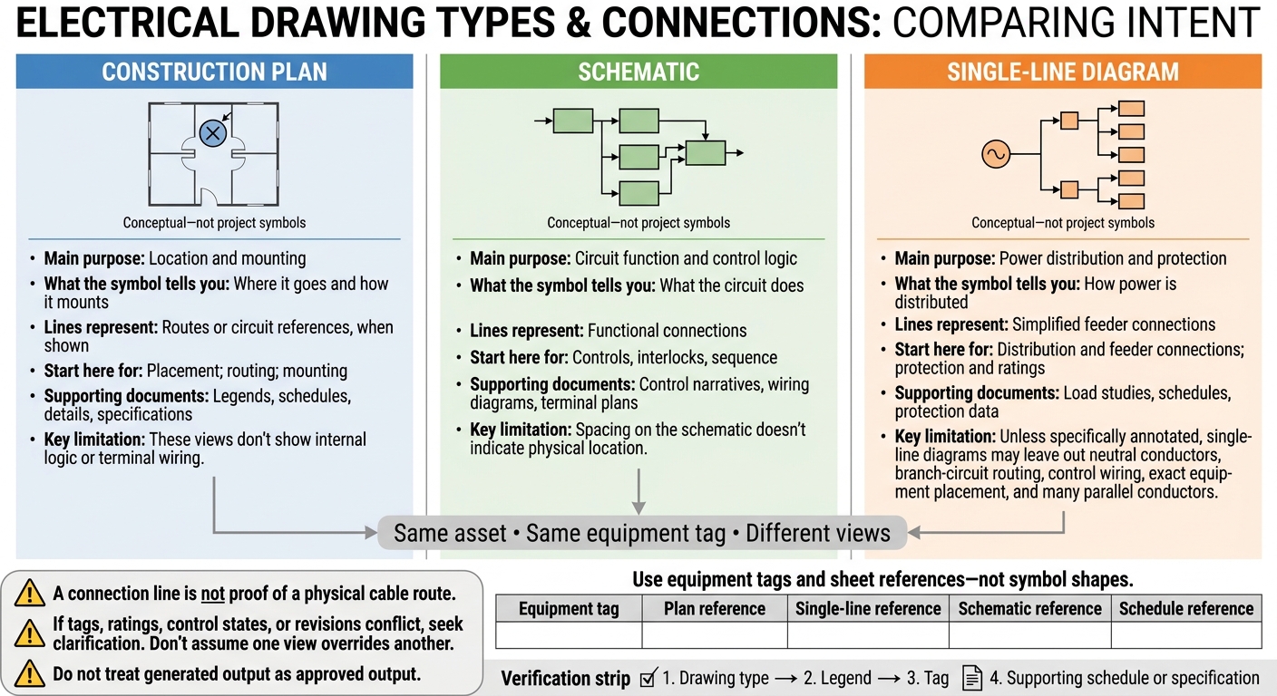
Compare drawing intent, not symbol shape. Each drawing serves a different purpose. The table shows typical content, but legends, notes, and references determine how to read it.
Use the same equipment tag across all three views. The drawing type tells you what the symbol means.
| Review characteristic | Construction plan | Schematic | Single-line diagram |
|---|---|---|---|
| What the symbol tells you | Where it goes and how it mounts | What the circuit does | How power is distributed |
| Conductor treatment | Branch-circuit routes, homeruns, or circuit references when shown | Functional connections; wire references where provided | Simplified feeder paths representing multiple conductors |
| Control logic | May identify controlled devices, but usually not the full sequence or interlocks | Primary focus | May show major control or protection functions, but not detailed control wiring |
| Power flow | Branch circuits serving devices or equipment | Circuit operation, not necessarily full distribution | Source-to-load relationships |
| Ratings and protection | Often supplied through schedules, notes, or specifications | Device data relevant to operation | System and equipment ratings where provided |
| Supporting references | Legends, schedules, details, specifications | Control narratives, wiring diagrams, terminal plans | Load studies, schedules, protection data |
These purposes explain why symbols aren't interchangeable across views. Keep that distinction in mind as you follow an equipment tag from one sheet to another.
Choose the Drawing for the Review Task
Start with the drawing that matches your task, then check the supporting documents.
| Review task | Start with | Check alongside it |
|---|---|---|
| Placement | Construction plan | Dimensions, architectural coordination, and access requirements |
| Routing | Construction plan | Whether routes are defined or conceptual; cable schedules and details |
| Mounting | Construction plan | Elevations, supports, mounting details, and specifications |
| Controls, interlocks, sequence | Schematic | Sequence of operations, wiring diagrams, and field-device locations |
| Distribution and feeder connections | Single-line diagram | Panel schedules, equipment schedules, and feeder references |
| Protection and ratings | Single-line diagram | Fault-current and coordination studies, and protective-device data |
Use more than one sheet: plans for placement, schematics for control, and single-lines for distribution and protection.
Find Details Missing From Each View
A detail absent from one view may appear in another. Use these references to find it.
| Missing detail | Next view |
|---|---|
| Plan: functional behavior or interlocks | Schematics, sequence of operations, and controls narrative |
| Plan: upstream supply and protection | Single-line diagram, panel schedules, and specifications |
| Schematic: field locations and mounting | Construction plans, equipment layouts, elevations, and details |
| Schematic: terminal-level field connections | Wiring diagrams, terminal plans, and manufacturer documentation |
| Single-line: individual conductors or control wiring | Wiring diagrams, schematics, cable schedules, and termination drawings |
| Any view: complete requirements | Equipment schedules, details, specifications, and approved submittals |
Before treating a detail as missing, check the drawing index, sheet references, schedules, and revision history. An omitted detail is not automatically an omitted scope item. If the coordinated documents still leave a requirement unclear, use the project's clarification process rather than infer it from a symbol. Follow the equipment tag and sheet reference to the next view.
Connect Drawings With Equipment Tags and References
Once you understand what each drawing shows, use tags and references to link the same equipment across sheets. A circuit number identifies a path, while a reference marker points to another sheet or detail. Consistent tags help with procurement, installation, and commissioning, but they don’t replace complete specifications.
Trace Equipment Tags Across Drawings
Use the equipment tag to match the same asset across plan, single-line, and schematic views. The tag identifies the asset; its symbol changes with the view.
Build a reference matrix with five columns: equipment tag, plan reference, single-line reference, schematic reference, and schedule reference. Enter actual sheet and detail numbers rather than assuming a match. Contacts and relays may have separate component IDs, so check their links through wire numbers, terminals, and equipment data.
MDP, MCC, ATS, GEN, TX, UPS, and LP commonly identify distribution panels, motor control centers, transfer switches, generators, transformers, uninterruptible power supplies, and lighting panels, respectively. Confirm each abbreviation in the project legend - not from memory.
Use the matrix before checking connections, ratings, and revisions.
Check Connections, Ratings, and Revisions
Start with the legend and notes. Identify the tag, trace it on the plan, check the single-line and schematic, then confirm the schedules and specifications. Check equipment names, feeder destinations, applicable ratings, control states and interlocks, and cross-references.
Compare revision clouds with issue dates and revision notes. Record each conflict, including the tag, sheets, revisions, and clarification needed. Don’t assume one view overrides another.
Run these same checks on any generated drawing set before approval.
Review Drawing Outputs From Elora Grid
Engineers can upload tender drawings and related documents to Elora Grid to generate 2D and 3D general arrangements, single-line diagrams, and schematics for bid and design outputs. Check symbol conventions for each view, tag consistency, connections, ratings, control states and interlocks, unresolved exceptions, and revision status.
Generated drawings still need engineering review. They don’t prove compliance, constructability, or coordination. Do not treat generated output as approved output.
Conclusion: Check Drawing Purpose, Symbols, and Tags
A drawing’s purpose determines what its symbols mean: construction symbols show installation, schematic symbols show control behavior, and single-line symbols show power distribution.
These views work together. Read each for its intended purpose, then connect them using equipment tags and sheet references - not symbol shapes.
Use the tag to confirm you’re looking at the same asset across views. Before relying on a symbol, check the drawing type, legend, tag, and supporting schedule or specification - in that order. A familiar shape alone doesn’t define the requirement.
FAQs
How do I interpret a symbol missing from the legend?
Don’t guess what the symbol means. Cross-check it against the project specifications and equipment list to confirm the component’s type, rating, and function. Then check the general arrangement for its physical location and installation context.
If the discrepancy remains or affects your cost estimate, document the missing information in a technical query to the client or as a formal qualification in your bid.
How can I trace equipment when tags don’t match?
Trace equipment by its identity and connections - not by symbols or tags. Put the single-line diagram (SLD) equipment counts, ratings, and drawing references in a table. Cross-check specifications and equipment lists against room locations and cable routing shown in general arrangement drawings. Confirm matches using bus/way, circuit references, terminals, wiring, or cores - not matching tags alone.
Record every mismatch as a clarification or qualification, and cite the exact drawing reference.
What should I do when plans and schematics conflict?
Treat discrepancies as items to clarify. Create a table that maps each symbol, rating, and reference. Check it against the project specifications and general arrangements, and list every disagreement.
Send the client a request for information before project close, or document the mismatches as formal qualifications in your bid. Elora Grid automatically identifies mismatches and cites the source document for each one.