
Linked 2D & 3D Electrical Drawings: Update Workflow
I treat a successful sync as a data transfer - not design approval. To keep linked 2D drawings and 3D models aligned, I use four steps: prepare, update, sync, and review.
- Prepare: Confirm approved revisions, shared equipment IDs, file paths, field mappings, and who owns each field.
- Update: Edit circuit logic and ratings in 2D; edit placement and routing in 3D. Preserve equipment IDs when items move.
- Sync: Transfer only supported fields in the approved direction. Record changes and resolve conflicts before publishing.
- Review: Check connections, physical fit, clearances, schedules, and warnings. Get approval, inspect the exported files, and archive the release.
My release rule: <u>no unresolved issues</u>. Whether you sync manually, automatically, or on a schedule, both views still need review before export.
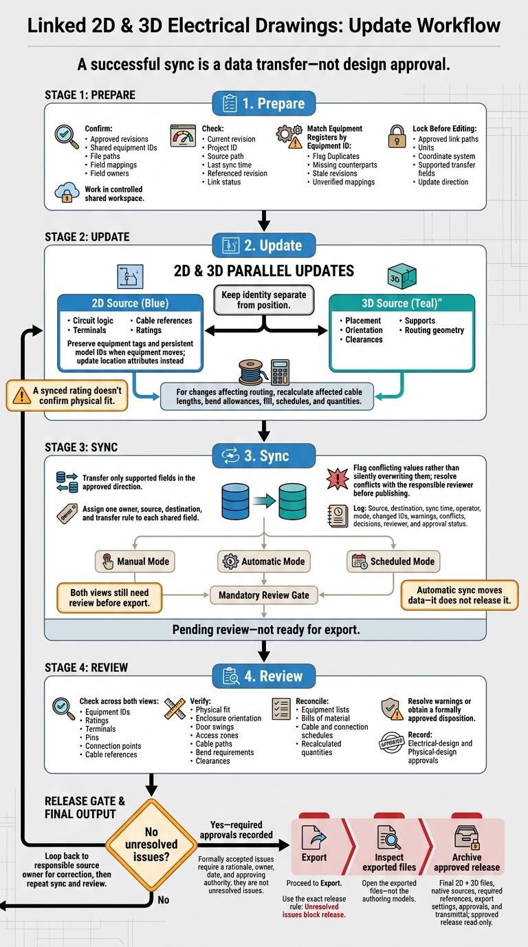
Linked 2D & 3D Electrical Drawings: Update Workflow
Prepare the Project and Equipment IDs
Check Revisions, Access, and Data Ownership
Work only in the controlled shared workspace, not in downloaded copies. Before editing, verify the current revision, project ID, source path, last sync time, and referenced revision. Check the link status, too. Leave disconnected copies untouched until you confirm the controlling source.
Match the drawing title block, equipment schedules, and specifications to the approved project baseline. This is especially critical when reading a single line diagram to scope substation or switchroom requirements. Filenames alone aren’t enough. Record the approval date and approver.
Check each contributor’s view, edit, approval, and release permissions. Divide data ownership clearly: the electrical designer owns circuit logic, terminals, cable references, and ratings in 2D. The 3D designer owns placement, orientation, clearances, supports, and routing geometry.
Before editing, log every pending change with its request number, affected equipment IDs, source reference, revision, owner, reviewer, and status.
Match Equipment IDs and Connection Details
Compare the 2D and 3D equipment registers by equipment ID. Flag duplicates, missing counterparts, stale revisions, and unverified symbol-to-component mappings right away.
Keep identity separate from position: when equipment moves, preserve its equipment tag and persistent model ID. Update the location attributes instead. Don’t assume export-only IDs will stay stable across applications or revisions.
| Identifier or attribute | 2D location | 3D location | Mismatch consequence |
|---|---|---|---|
| Equipment ID | Symbol and equipment schedule | Component properties | Updates may attach to the wrong item |
| Location code | Installation or location field | Room, enclosure, or mounting location | Installation area may be incorrect |
| Terminals, pins, and cable references | Schematic connection data | Physical connection points and routed cables | Wiring or termination may be incorrect |
| Ratings and part data | Device properties and parts list | Component type and manufacturer data | Equipment selection or dimensions may differ |
For each equipment ID, check that the mapped component matches the equipment class and connection arrangement - not just the tag. Log every mismatch with both values, source files, an owner, and a disposition. Keep unverified mappings flagged rather than accepting them without review.
Identify simplified geometry that needs replacement or approval before release. Once the IDs and connections match, lock down the sync settings.
Check Elora Grid Outputs Against Approved Project Data
Compare the generated equipment IDs, revisions, ratings, terminal or cable references, locations, and model data against the approved equipment register and baseline.
If Elora Grid generated the deliverables, treat them as project data to review - not proof of synchronization. Have the assigned electrical and 3D reviewers record accepted corrections in the controlled project system.
After the baseline matches the approved data, set the link paths and update direction before editing. For more technical walkthroughs, see our guides for bid and tender teams.
sbb-itb-f008923
Set Up Synchronization Before Editing
Once the baseline and equipment IDs align, lock the sync settings before editing.
Check Link Paths, Field Mappings, and Update Direction
Confirm the approved link path, exchange format, coordinate system, units, software version, and update direction. Record the exchange direction and responsible approver. Set the shared coordinate system from one authoritative file, then apply it consistently to related files.
Before editing, create a mapping table that assigns one owner, source, destination, and transfer rule to each shared field. Specify whether each field uses one-way or two-way synchronization, or stays out of the exchange. Keep circuit logic authoritative in 2D, and placement and routing authoritative in 3D. Follow approved project notation for voltage, dimensions, and cable sizes.
Handle geometry, graphics, calculated values, and notes separately; they may not transfer reliably. Flag conflicting values for review rather than silently overwriting them. Test uncertain mappings in a controlled copy before enabling the shared link, and compare the results with what you expected.
Once the mapping is locked, edit each field only in its owning source.
Choose Manual, Automatic, or Scheduled Synchronization
Use only a sync mode your workflow supports, and time it around the project’s review gates. Automatic sync moves data - it does not release it.
| Mode | Best use | Review requirements | Conflict risk | Revision tracking |
|---|---|---|---|---|
| Manual | Early design or complex changes | Review each change set and target revision | Large batches can have a high impact | Record operator, revisions, date, and result |
| Automatic | Frequent, low-risk updates | Monitor warnings, review regularly, and restrict release permissions | Overwrites that escape review, duplicate tags, or stale links | Retain logs linked to project revisions |
| Scheduled | Coordination or fixed publishing cycles | Review queued changes and notify affected teams | Contributors may edit different revisions | Label each batch with date, revision, and scope |
Manage Offline Edits and Revision Records
Use reservation or check-out controls where supported. Before reconnecting offline work, save the local file, identify its base revision, and compare it with the current shared revision. Reconcile changes that don’t conflict first. Then resolve conflicts one at a time with the responsible discipline.
Work in a new revision rather than overwriting the shared file. Keep the offline copy until reconciliation is approved.
- Broken link: Stop synchronization. Check the approved path, file name, permissions, and source revision before relinking. Record the reason before creating any replacement link.
- Disconnected work: Save the local file and identify its base revision. Reconcile its changes against the current shared revision before publishing.
- Duplicate equipment ID: Stop the exchange. Determine whether the item is duplicated or incorrectly tagged, then assign an approved ID that no other item uses before synchronizing.
- Unresolved conflict: Reject both values until the reviewer approves one. Record the decision and synchronize only after approval.
Log the source, destination, sync time, operator, mode, changed IDs, warnings, conflicts, decisions, reviewer, and approval status. Record the sync result and warning count in the project record.
After clearing conflicts, apply the approved changes in the owning source first.
Apply Changes in the Right Order
With sync settings locked, follow source edit, sync, review before export. Start with the latest approved linked files, trace the affected equipment IDs, and edit the owning source first.
Update Circuit Logic in the 2D Source Drawing
Update circuit topology, protective-device ratings, and connection points in the schematic or single-line diagram. Once those changes are approved, push only supported downstream fields into the 3D model. Then check the receiving equipment record.
A synced rating doesn’t confirm physical fit. Check enclosure size, mounting, cable entry, access clearance, and weight against the approved equipment data.
Update Equipment Placement and Routing in 3D
Edit coordinates, enclosure arrangement, and physical routes in 3D. Before sending supported location and route data back to drawings, recalculate affected cable lengths, bend allowances, fill, schedules, and quantities.
Use 1 ft = 304.8 mm and 1 in = 25.4 mm. Round schedule values only after calculation.
Coordinate Changes That Affect Both 2D and 3D
Follow this pattern when a change affects both views:
Example: When relocating equipment, preserve its shared ID, update placement and routing in 3D, and carry any route-length change - such as 45 ft to 51 ft, measured along the revised path - into the feeder schedule and quantity check.
Transfer supported updates, then check clearances, bend space, and voltage-drop inputs. If values conflict, use the owning source’s approved value, record why the other value was rejected, and recalculate dependent data.
Save both files under one revision ID. Include old and new values, changed IDs, recalculated schedules, editor, reviewer, date, and status. Mark the package pending review - not ready for export.
Review the Synchronized Revision Before Export
Compare the synchronized draft with the last approved issue before release. Confirm that the linked 2D source and 3D model still show the same approved electrical design.
Check Equipment, Connections, and Clearances
Use shared equipment IDs to compare affected items. Check that 2D symbols match their 3D instances, including ratings, locations, terminals, pins, connection points, and cable references. Record schematic-only symbols and logical loads as intentional exceptions - not missing equipment.
Check enclosure orientation, door swings, access zones, cable paths, and bend requirements against project criteria and the applicable NFPA 70 edition. Review nearby structure, piping, and equipment. Where combined discipline models are available, run targeted clash checks. These checks support the review, but working clearances and access zones still need direct verification.
Once geometry and clearance checks pass, reconcile schedules and address sync warnings.
Reconcile Schedules and Resolve Sync Warnings
Compare equipment lists, bills of material, and cable and connection schedules. Confirm that affected quantities have been recalculated, and investigate any unexplained differences.
Trace each sync warning to its object and source field, then resolve it or document its disposition. Mark each item as resolved, accepted by the approver, or unresolved. Accepted issues need a rationale, owner, date, and approving authority. Unresolved issues block release.
Check titles, revision blocks, issue status, file names, and units against the document register and title block. Don't rely on file names alone.
Release only when every warning is resolved or formally dispositioned.
Approve, Export, and Archive the Release
Before export, confirm the approved sync direction and software environment. Verify that references between 2D symbols and 3D instances are reconciled and that the export package is complete, including available linked references.
Confirm that clearances and affected schedules have been checked and that warnings are resolved or formally dispositioned. Record electrical-design and physical-design approvals, including reviewer names and approval dates. Then export only the approved issue for final inspection and archiving.
Open the exported files - not the authoring models. Inspect every sheet or view for missing references, clipped text, unreadable annotations, incorrect line weights, broken symbols, empty views, wrong scale, incorrect units, and incomplete legends. For 3D exports, also check model visibility, object categories, coordinates, levels, section boxes, linked models, and measurement behavior.
Archive the final 2D and 3D files together with native sources, required linked references, export settings, approvals, and the transmittal. Keep the approved release read-only and separate from working files and superseded revisions.
Summary: Keep 2D and 3D Updates Under Control
Keep the workflow simple: use shared equipment IDs as the reference, manage electrical logic in the 2D source, and keep geometry in 3D.
Update the authoritative 2D source first, then push approved changes to 3D. If a change starts with a 3D edit, route it through the approved 2D-to-3D update workflow. Don’t treat 3D as the source of record.
Check that both views match, and store revision history and approval records in the controlled project system. Export only after the synchronized revision has been checked and approved.
FAQs
How do I handle equipment replacements without losing revision history?
Use the system’s automated, auditable change log to save every drawing version without overwriting earlier revisions. You can then review past versions and see what changed, when it changed, and why.
When replacing equipment, use consistent tags across 2D plans, 3D models, single-line diagrams, and schematics. These tags keep views linked and in sync, so you can track the equipment’s identity and connections while keeping its revision history intact for audits.
What if my software cannot sync a required field?
Before treating information as missing, check equipment tags and sheet references across the plan, single-line diagram, and schematic. The detail may appear in another view.
If the coordinated documents don’t include it, follow the project’s formal clarification process. Record the conflict and request official guidance instead of guessing. This helps keep documentation consistent, project details accurate, and work compliant.
How do I roll back an incorrect sync?
Use the built-in change-tracking log to undo an incorrect sync. Every revision is saved automatically as you draft your drawings, so no data gets overwritten.
Check the history to see what changed, when, and why. Then select and open an earlier version to restore your project to that state.