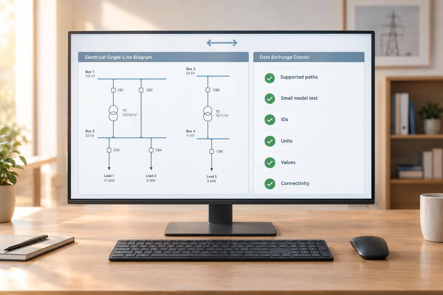
ETAP DataX: Electrical Data Exchange Checks
I don’t treat a completed ETAP DataX import as proof that the model is correct. Before using it for design or bid work, I check four things: equipment IDs, electrical values, units, and connectivity - with zero missing required IDs and no unexplained changes.
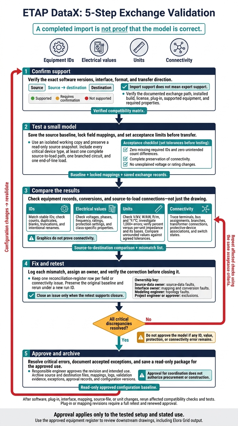
My check follows five steps:
- Confirm support: Verify the exact software versions, interface, format, and transfer direction. Import support does not mean export support.
- Test a small model: Save the source baseline, lock field mappings, and set acceptance limits before transfer.
- Compare the results: Check equipment records, conversions, and source-to-load connections - not just the drawing.
- Fix and retest: Log each mismatch, assign an owner, and verify the correction before closing it.
- Approve and archive: Resolve critical errors, document accepted exceptions, and save a read-only package for the approved use.
I use the approved equipment register to review downstream single line diagrams, including Elora Grid output. <u>Approval applies only to the tested setup and stated use</u> - and I require a full retest and renewed approval after plug-in or mapping changes.
ETAP DataX: 5-Step Exchange Validation
ETAP-Revit Data Exchange
sbb-itb-f008923
1. Verify Supported Exchange Paths and Versions
List each exchange as source → destination, with separate entries for import, export, and bidirectional workflows. Import support does not imply export support. Apply this rule when filling in the compatibility matrix, before running any test exchange.
Check Vendor Documentation and Interface Requirements
Check ETAP release notes, interface guides, installation instructions, and plug-in documentation against the installed build, license, supported equipment, and required properties. For Revit, confirm the DataX add-in, required interface module, installation sequence, and WCF communication requirements.
For Excel, check worksheet mappings, consistency checks, blank-value rules, and default substitutions. For CIM XML, record the CIM version, namespace, required classes and attributes, and IEC 61970 or IEC 61968 profile. A profile defines the subset of CIM used for a specific exchange.
Build a Compatibility Matrix
Use one row for each direction and version combination. Record the exact documentation source, version, date checked, and status. This table is a fill-in template, not a claim of support. Confirm compatibility before checking IDs, voltages, units, and connectivity.
| Exchange path | Source → destination | ETAP release | Source-software version | Plug-in version | Project or exchange format | Exchange method | Documentation URL and section | Verification date | Status |
|---|---|---|---|---|---|---|---|---|---|
Enter a verification date only after checking the evidence. Mark Supported when documentation confirms the exact workflow and versions, or Not supported when it explicitly excludes them. Otherwise, keep Requires confirmation. Log any conflicts and request clarification.
Use the completed matrix to select the exact test model and settings for the next step, then run a controlled test model.
2. Prepare and Exchange a Test Model
Use a small, isolated project copy - not the production model - so you can preserve evidence for comparison. Keep a read-only source snapshot and a separate working copy. Use the exact ETAP, plug-in, source-app, OS, Excel, and mapping-file versions verified in Section 1. Record the operator, file names, and test date in MM/DD/YYYY format.
Once the supported path is fixed, test the smallest model that includes every critical device type.
Record Equipment and Field Mappings
Build a compact sample with one source, transformer, bus or switchboard, panel, feeder, load, protective device, and cable, where supported. Include at least one complete source-to-load path, one branched circuit, and one end-of-line load.
Before the exchange, record expected counts, stable IDs, parent or location fields, voltages, phases, frequency, ratings, units, library references, and connection endpoints. Match records by stable IDs, not names alone.
For each source field, record its data type, target element and property, conversion rule, and validation method. Label the field as required, optional, derived, defaulted, or excluded. Specify whether equipment should be created, matched, skipped, or substituted. For any default or library substitution, record the original value, replacement value, reason, and approval requirement.
Lock the mapping rules and set acceptance criteria before running the test:
- Zero missing required IDs and zero unintended count differences.
- Complete preservation of connectivity.
- No unexplained voltage or rating changes.
Set rounding and tolerance limits using project requirements and documented interface precision. List intentional exclusions separately so they don't hide missing data.
Run the Exchange and Save Test Records
Follow the verified procedure without making undocumented edits during transfer. Record start and end times, review recognition and mapping decisions, and keep the consistency-check results.
Save the source snapshot, mapping settings, destination model, warnings, errors, and any generated one-line diagram for comparison. For Excel exchanges, also keep the original workbook and exact worksheet-to-element map.
If there's no formal log, take screenshots and write the test record immediately. Test reverse exchange separately, using a new file, and only when the documented path supports it.
Use these records in the next step to check IDs, values, units, and connectivity.
3. Check IDs, Electrical Values, and Connections
Use the saved test records from Section 2 to compare the destination model with the saved baseline before using it for any study or procurement.
Compare Equipment IDs and Electrical Properties
Compare equipment count, type, stable ID, description, location, status, and the fields needed for the intended study or procurement. Use both exact and normalized string matching to find missing, duplicate, blank, truncated, case-only, or punctuation-altered stable IDs.
For intentional renames, keep a source-to-destination mapping that records the reason, approver, and date. Matching counts alone do not validate a rename. These checks help separate true matches from records that were defaulted, substituted, or renamed.
Check voltage basis, phase configuration, frequency, equipment ratings, interrupting and withstand ratings, transformer ratio and impedance, conductor or cable data, protective-device settings, and operating status. Keep the class-specific checks:
Check transformer winding connections and taps, motor horsepower and efficiency, bus ratings, breaker trip settings, and load power factor.
Mark each field as matched, changed, unmapped, substituted, rejected, or not applicable.
Inspect the destination properties - not just the import summary. A populated field may contain a default value, so every replacement needs engineering review.
Verify Units and Numerical Conversions
Compare both values and unit labels: V/kV, W/kW, ft/m, and °F/°C. Keep the project’s documented units and U.S. number format. Check line-to-line versus line-to-neutral voltage separately from unit conversions.
Independently recalculate representative conversions and investigate 1,000× errors. Verify percent versus per-unit impedance, including its voltage and MVA bases.
Compare unrounded values against agreed, field-specific tolerances. Don’t dismiss changed protective settings as display rounding. Apply the same tolerances when reviewing connection and protection data that depends on converted values.
Trace Source-to-Load Connections
Trace the test model’s energized, branched, transformer-fed, and intentionally open paths through every bus, switch, breaker, transformer, feeder, and load. Check terminal assignments, bus membership, primary and secondary connections, protective-device associations, and transferred switch states.
Graphics do not prove connectivity. Verify terminals, bus assignments, circuit references, node IDs, and consistency checks.
Record the source and destination paths, expected and observed states, and review decision. Also document any islands, floating equipment, missing branches, reversed transformer connections, or loads on the wrong bus. Record each mismatch for the reconciliation register in the next step.
4. Record Discrepancies and Retest Corrections
Start the reconciliation register with the mismatches found in Section 3.
Track Field Differences in a Reconciliation Register
Create one row per field or connectivity issue and link it to the saved exchange run. Record the interface, plug-in, ETAP version, mapping revision, and exchange scope. Verify any defaulted or substituted value before closing its row.
Use only these statuses: Matched, Missing, Changed, Defaulted, Unmapped, Connectivity error. Classify each issue as Cosmetic, Engineering, or Intentional exclusion.
Approved unit conversions, naming changes, and unsupported display attributes count as Cosmetic only if traceability remains intact. Treat changes to identity, ratings, protection, phase, grounding, or connectivity as Engineering.
Include the corrective action, correction owner, retest date, approval date, and closure status in every row. For intentional exclusions, also record the excluded field, documented reason, and approver. Keep the row open until engineering confirms that the omitted information isn't required.
Source equipment ID Destination equipment ID Element type Field name Source value and unit Destination value and unit Status Issue type Corrective action Correction owner Retest date Approval date Closure status MTR-05 MTR-05 Motor Rated HP 50 hp 37.3 kW Matched Cosmetic - unit conversion verified Document the equivalent conversion and retain traceability Interface owner 10/14/2026 10/15/2026 Closed BKR-01 CB-101 Circuit breaker Rated kV 11 kV 13.8 kV Changed Engineering - voltage class changed Correct the mapping or source data, then rerun Interface owner 10/15/2026 Pending Open T-02 TR-02 Transformer Vector group Dyn11 Absent Missing Engineering - source field not populated Restore the source field or document an approved exclusion Source-data owner 10/16/2026 Pending Open SWG-01 SWG-01 Switchgear Internal arc rating Yes Defaulted Defaulted Engineering - no mapping for arc rating Add the mapping or confirm an intentional exclusion Interface owner 10/15/2026 Pending Open CBL-10 L-10 Cable Length 150 m 150 m Connectivity error Engineering - orphaned node at destination Repair the terminal assignment and rerun Modeling engineer 10/16/2026 Pending Open
Correct Mappings and Repeat Affected Checks
Once you've logged an issue, correct only the affected mapping or model element in the working copy. Assign each correction to the right owner:
- Source-data owner: source-data faults.
- Interface owner: mapping and conversion faults.
- Modeling engineer: topology faults.
- Project engineer or approver: exclusions.
Keep the original baseline unchanged. Apply corrections in a working copy, then rerun from that baseline under a new run ID.
Compare the new register with the previous run using the same field inventory and status rules. Recount equipment by element type and confirm one-to-one source-to-destination IDs. Repeat every affected check for ratings, voltage, frequency, phases, units, protection settings, and connectivity.
Close an issue only when the retest supports closure. Resolve every critical warning before engineering sign-off.
5. Approve and Archive the Checked Model
Have the responsible engineer approve the exchanged model, with input from the exchange checker and BIM/CAD coordinator. State the approved revision and its intended use. Approval for coordination does not authorize procurement or construction.
Accept only documented exceptions that do not affect the approved use. For each exception, record its ID, affected equipment, technical impact, compensating action, owner, due date, and approver. Do not approve the model if any ID, value, protection, or connectivity error remains. Once approved, lock the records and archive the controlled baseline.
Save Approval Records and Retest After Changes
Archive the source file, ETAP project, exported files, test model, mapping table, logs, validation reports, exception register, checklist, approval record, and the versions used to verify compatibility. Record the project units, exchange direction, test date and time, reviewers, and file hashes or controlled revision IDs.
Keep the approved package read-only and retain earlier revisions. Record its storage location, retention period, and document owner. This package serves as the configuration baseline.
After any change to software, plug-ins, interfaces, mappings, source files, or units, rerun the affected compatibility checks and tests. Plug-in or mapping revisions require a full retest and renewed approval before broader use.
Use Checked Equipment Records for Drawing Review
Use the approved equipment register from the checked ETAP model as the reference for reviewing downstream drawings generated in Elora Grid. Elora Grid generates electrical drawings - including general arrangements, single-line diagrams, and schematics - from uploaded tender drawings and related documents. Use the register only as a downstream drawing-review reference.
Give the drawing reviewer the approved register revision and any accepted exceptions. Compare equipment IDs, descriptions, voltage levels, ratings, feeder destinations, and connectivity against the checked ETAP model and project source documents.
Before bid or design release, verify incomer and feeder identities, bus and transformer connections, protective-device information, and equipment counts. Resolve discrepancies against the controlled model and source documents before issuing the output.
Conclusion: Confirm Compatibility and Resolve Critical Errors
Before exchanging models, confirm the vendor-supported exchange path and versions. Use a controlled test model to check IDs, values, units, and connectivity. Log every discrepancy.
If baseline study results are available, compare them with the converted model’s load-flow and short-circuit results.
Close all critical discrepancies before approval, and document the disposition of each minor exception. Archive the evidence with the approved revision, and revalidate after workflow changes. Approval applies only to the tested configuration.
FAQs
What if exchange documentation conflicts with my test results?
Report every discrepancy. Immediately log any contradiction, ambiguity, or gap in your conflict and variation register. Submit it as a formal clarification or record it as a departure from the requirements. For each mismatch, include clear references to the test records and the specific exchange document clauses or drawings involved.
How do I set tolerances for electrical data checks?
Use your site-specific design basis to set tolerance limits when checking equipment IDs, voltage values, units, and connectivity against single-line diagrams (SLDs) and general arrangements (GAs).
Check vendor documentation to confirm supported exchange paths, versions, file formats, and protocol standards. For each missing or changed field, record the source document and page number so others can trace it back.
How can I detect connectivity errors in a large model?
Start by creating a document register organized by title-block revision markers. This helps confirm you’re reviewing the latest versions. Then use automated conflict detection tools to flag discrepancies between drawings and the project scope.
Compare schematics, general arrangements, and specifications clause by clause or component by component to spot gaps, contradictions, and ambiguities. Log each finding in a conflict and variation register, linking it to the source document and page so it’s easy to trace.