GA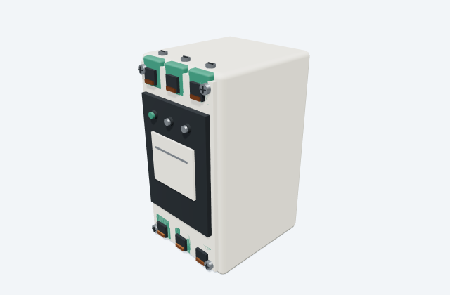
Relay socket
A relay socket supports a plug-in relay and its associated connections.
General arrangement objects
In plain English
70170-D is the drawing identifier for control-device socket or base in AutomationDirect's Timers and Sockets collection. A socket or base provides the mounting and connection interface for a compatible control device. Its drawing does not identify every device that could physically appear to fit it.
For example, in a microgrid installation with a control panel where a plug-in device can be replaced without disturbing field wiring, use the 70170-D reference to coordinate socket terminals, retaining parts and plug-in removal route. Show the neighbouring equipment and the connection route so the installer can understand the intended arrangement.
Use the reviewed native drawing identified as Relays and Timers/Timers and Sockets/70170-D.DWG for the exact physical details. Locate the named file in its original manufacturer archive. Manufacturer drawing previews are shown only when an exact approved source is available. Any illustrative 3D view is a separate concept and is not to scale; use the selected manufacturer documents for dimensions, ratings and installation details.
Read the source: AutomationDirect Timers and Sockets official CAD source
An original 3D illustration of this equipment type. Rotate and zoom to explore its shape. It does not represent an exact manufacturer model or dimensional layout.
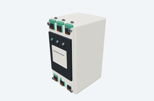
Drag to rotate · Scroll or pinch to zoom · Original educational visualisation. Relative proportions; use the selected manufacturer drawing for dimensions.
70170-D is the drawing identifier for control-device socket or base in AutomationDirect's Timers and Sockets collection. A socket or base provides the mounting and connection interface for a compatible control device. Its drawing does not identify every device that could physically appear to fit it.
For example, in a control panel where a plug-in device can be replaced without disturbing field wiring, use the 70170-D reference to coordinate socket terminals, retaining parts and plug-in removal route. Show the neighbouring equipment and the connection route so the installer can understand the intended arrangement.
Use the reviewed native drawing identified as Relays and Timers/Timers and Sockets/70170-D.DWG for the exact physical details. Locate the named file in its original manufacturer archive. Manufacturer drawing previews are shown only when an exact approved source is available. Any illustrative 3D view is a separate concept and is not to scale; use the selected manufacturer documents for dimensions, ratings and installation details.
This reference concerns the named 70170-D drawing and its control-device socket or base role. A drawing in the same collection is not automatic evidence of compatible terminals, mounts or electrical performance.
These public references support the explanation and provide further detail. Their graphics and downloadable files remain with their publishers.
Official source collection and exact native drawing identity, with the equipment role checked against native content or the narrowly defined source family.
A relay socket supports a plug-in relay and its associated connections.
A maintenance envelope represents the selected space needed for servicing an item.
Elora Grid helps electrical teams work with drawings, specifications and equipment information. Explore the drafting workflow or join the early-access waitlist.