U/I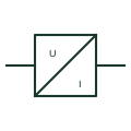
Voltage measuring transducer
Transducer that converts a VT secondary or direct voltage into an isolated analogue signal for remote measurement.
Schematic
Measuring transducer that converts CT and VT inputs into a DC signal proportional to active power for SCADA or control.
In plain English
An active-power device that turns a measured quantity into a signal takes current and voltage inputs and produces a DC current or voltage signal proportional to watts, often bipolar so that export and import give opposite signs. It is used where a governor, load controller or older SCADA needs an analogue power signal.
The output range, including how negative power is represented, must match the receiving input. The symbol shows the conversion but not the element configuration, response time or the scaling between rated power and output signal.
Check how reverse power is represented at the output. Confirm element configuration matches the system wiring. An active-power device that turns a measured quantity into a signal outputs a signal; an active power indicator displays the value.
Measuring device that turns a measured quantity into a signal that converts CT and VT inputs into a DC signal proportional to active power for SCADA or control. An active-power device that turns a measured quantity into a signal outputs a signal; an active power indicator displays the value.
Read the source: Analog current signal isolation · IEC graphical symbols for diagrams
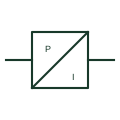
An active-power transducer takes current and voltage inputs and produces a DC current or voltage signal proportional to watts, often bipolar so that export and import give opposite signs. It is used where a governor, load controller or older SCADA needs an analogue power signal.
The output range, including how negative power is represented, must match the receiving input. The symbol shows the conversion but not the element configuration, response time or the scaling between rated power and output signal.
An active-power transducer outputs a signal; an active power indicator displays the value.
These public references support the explanation and provide further detail. Their graphics and downloadable files remain with their publishers.
Public context for analogue measuring signals and their isolation.
IEC context for graphical symbols used in diagrams; no IEC graphic is reproduced.
This illustration was authored independently by Elora Grid to explain the concept. It is not reproduced from a customer drawing, an official standard graphic or a manufacturer CAD file. Its correspondence to an exact IEC or IEEE symbol identifier has not been certified.
SVG and DXF downloads contain this original artwork. DXF uses unscaled drawing units; a GA envelope supplies no product dimensions, clearances or fabrication information. Original artwork is available under CC BY 4.0. Third-party references retain their own terms.
Transducer that converts a VT secondary or direct voltage into an isolated analogue signal for remote measurement.
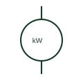
An active-power indicator displays real power derived from its specified measurement inputs.
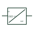
A current signal isolator transfers a documented analog current input to an output while providing the specified electrical separation.
Elora Grid helps electrical teams work with drawings, specifications and equipment information. Explore the drafting workflow or join the early-access waitlist.