CT PRI
Current transformer with primary conductor indication
This CT representation explicitly identifies the primary conductor passing through the measurement location.
SLD / Schematic
IEEE-library CT form that shows the primary conductor passing through the core, as with window and bar-type CTs.
In plain English
This CT form draws the primary conductor explicitly passing through the transformer core. It suits window, bar and bushing CTs where the primary is the main circuit conductor itself, and it helps the reader see which conductor, and how many passes, the CT encloses.
The conductor indication does not give ratio, accuracy class or burden. If the primary passes the window more than once, the effective ratio changes, so turns through the window must be noted beside the symbol.
Count primary passes through the window. Check polarity marks against the primary current direction. The conductor-indication form shows the enclosed primary; the plain CT form represents the CT without showing how the primary is arranged.
IEEE-library CT form that shows the primary conductor passing through the core, as with window and bar-type CTs. The conductor-indication form shows the enclosed primary; the plain CT form represents the CT without showing how the primary is arranged.
Read the source: Autodesk IEEE Symbol Preview — Current Transformers · IEEE/ANSI 315-1975: graphic symbols for electrical and electronics diagrams
Autodesk publishes this block under its IEEE Symbol Preview. The counterpart is the matching functional concept in the library; no equivalence of every detailed standard graphic is asserted.
Shown as an independently authored educational illustration. Use the cited publication and drawing legend to verify the required drafting form.
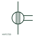
This CT form draws the primary conductor explicitly passing through the transformer core. It suits window, bar and bushing CTs where the primary is the main circuit conductor itself, and it helps the reader see which conductor, and how many passes, the CT encloses.
The conductor indication does not give ratio, accuracy class or burden. If the primary passes the window more than once, the effective ratio changes, so turns through the window must be noted beside the symbol.
The conductor-indication form shows the enclosed primary; the plain CT form represents the CT without showing how the primary is arranged.
These public references support the explanation and provide further detail. Their graphics and downloadable files remain with their publishers.
Public IEEE-oriented Current Transformers preview listing the With Conductor Indication block.
Graphic-symbol standards context and official status; not a source of reproduced artwork.
This illustration was authored independently by Elora Grid to explain the concept. It is not reproduced from a customer drawing, an official standard graphic or a manufacturer CAD file. Its correspondence to an exact IEC or IEEE symbol identifier has not been certified.
SVG and DXF downloads contain this original artwork. DXF uses unscaled drawing units; a GA envelope supplies no product dimensions, clearances or fabrication information. Original artwork is available under CC BY 4.0. Third-party references retain their own terms.
This CT representation explicitly identifies the primary conductor passing through the measurement location.
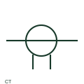
IEEE-oriented graphical reference for current transformer, with public vendor evidence and drawing-reading notes.

Toroidal CT mounted around a transformer or breaker bushing, often with a tapped multi-ratio secondary.
Elora Grid helps electrical teams work with drawings, specifications and equipment information. Explore the drafting workflow or join the early-access waitlist.