SD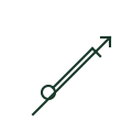
Dimmer switch plan mark
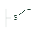
Plan mark for a switch that varies lamp brightness, drawn as a switch with an added variability arrow.
IEC
US plan symbol SD for a wall dimmer controlling a lighting group.
In plain English
A wall dimmer in US plan practice is drawn as S with subscript D, sometimes with a wattage note. The switch leg links it to the dimmed group, and three-way dimming is shown by pairing SD with S3 or with a companion device.
The reader should check dimmer type against LED driver compatibility, and whether the dimmer controls a low-voltage 0-10 V signal or switches line power directly. The plan symbol is identical for both. SD does not specify dimming technology, load or whether multi-gang derating applies.
Check dimming technology in the fixture schedule. Note multi-gang derating for ganged dimmers. The IEC dimmer uses a variability arrow on a switch mark; the US form uses the D subscript.
US plan symbol SD for a wall dimmer controlling a lighting group. The IEC dimmer uses a variability arrow on a switch mark; the US form uses the D subscript.
Read the source: IEEE/ANSI 315-1975: graphic symbols for electrical and electronics diagrams
US architectural electrical plan practice in the ANSI Y32.9 lineage, read alongside IEEE 315 context; independently drawn, not a certified IEEE or ANSI graphic.
Shown as an independently authored educational illustration. Use the cited publication and drawing legend to verify the required drafting form.
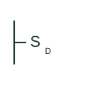
A wall dimmer in US plan practice is drawn as S with subscript D, sometimes with a wattage note. The switch leg links it to the dimmed group, and three-way dimming is shown by pairing SD with S3 or with a companion device.
The reader should check dimmer type against LED driver compatibility, and whether the dimmer controls a low-voltage 0-10 V signal or switches line power directly. The plan symbol is identical for both. SD does not specify dimming technology, load or whether multi-gang derating applies.
The IEC dimmer uses a variability arrow on a switch mark; the US form uses the D subscript.
These public references support the explanation and provide further detail. Their graphics and downloadable files remain with their publishers.
Graphic-symbol standards context; not a source of reproduced artwork.
This illustration was authored independently by Elora Grid to explain the concept. It is not reproduced from a customer drawing, an official standard graphic or a manufacturer CAD file. Its correspondence to an exact IEC or IEEE symbol identifier has not been certified.
SVG and DXF downloads contain this original artwork. DXF uses unscaled drawing units; a GA envelope supplies no product dimensions, clearances or fabrication information. Original artwork is available under CC BY 4.0. Third-party references retain their own terms.
Elora Grid helps electrical teams work with drawings, specifications and equipment information. Explore the drafting workflow or join the early-access waitlist.