BOND FE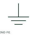
Functional equipotential bonding
Functional equipotential bonding connects documented points for an operational or signal-related purpose.
SLD / Schematic
IEEE-oriented functional equipotential bond used to keep equipment at a common reference for operation or noise control.
In plain English
A functional equipotential bond ties equipment together for operational reasons, such as keeping communications equipment at a common reference or reducing high-frequency noise. The publisher's IEEE miscellaneous preview lists a functional equipotential bond form, the counterpart of the existing IEC concept page.
This illustration is an independent explanation and not the IEEE graphic. A functional bond does not satisfy protective bonding requirements unless it is also sized and installed as a protective conductor. Drawings should not use the functional form where a safety bond is intended.
Do not treat a functional bond as a protective one. Check high-frequency bonding requirements for drives and comms. A functional bond supports operation; a protective bond provides safety during faults.
IEEE-oriented functional equipotential bond used to keep equipment at a common reference for operation or noise control. A functional bond supports operation; a protective bond provides safety during faults.
Read the source: Autodesk IEEE Symbol Preview — Miscellaneous · IEEE/ANSI 315-1975: graphic symbols for electrical and electronics diagrams
Autodesk publishes this block under IEEE Symbol Preview: Miscellaneous. The counterpart is the matching functional concept; no equivalence of every detailed standard graphic is asserted.
Shown as an independently authored educational illustration. Use the cited publication and drawing legend to verify the required drafting form.

A functional equipotential bond ties equipment together for operational reasons, such as keeping communications equipment at a common reference or reducing high-frequency noise. The publisher's IEEE miscellaneous preview lists a functional equipotential bond form, the counterpart of the existing IEC concept page.
This illustration is an independent explanation and not the IEEE graphic. A functional bond does not satisfy protective bonding requirements unless it is also sized and installed as a protective conductor. Drawings should not use the functional form where a safety bond is intended.
A functional bond supports operation; a protective bond provides safety during faults.
These public references support the explanation and provide further detail. Their graphics and downloadable files remain with their publishers.
Exact public IEEE-oriented category page listing the functional equipotential bond form.
Graphic-symbol standards context and official status; not a source of reproduced artwork.
This illustration was authored independently by Elora Grid to explain the concept. It is not reproduced from a customer drawing, an official standard graphic or a manufacturer CAD file. Its correspondence to an exact IEC or IEEE symbol identifier has not been certified.
SVG and DXF downloads contain this original artwork. DXF uses unscaled drawing units; a GA envelope supplies no product dimensions, clearances or fabrication information. Original artwork is available under CC BY 4.0. Third-party references retain their own terms.
Functional equipotential bonding connects documented points for an operational or signal-related purpose.

IEEE-oriented protective equipotential bond, connecting exposed metal parts together for safety.
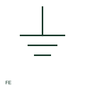
IEEE-oriented graphical reference for functional earth, with public vendor evidence and drawing-reading notes.
Elora Grid helps electrical teams work with drawings, specifications and equipment information. Explore the drafting workflow or join the early-access waitlist.