X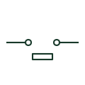
Bolted connecting link, open
A bolted connecting link drawn removed, showing a deliberate open point that needs tools and a dead circuit to close.
SLD / Schematic
A bolted bar link providing a removable connection, shown closed, that can only be opened with tools and no load.
In plain English
A bolted connecting link is a short removable bar between two conductors. It appears in switchboards to separate sections for testing or maintenance, as the generator neutral link, and in CT and VT circuits for isolation. The closed form shows the normal service state.
Unlike a disconnector, a link has no operating mechanism or rated breaking or making capacity. It must only be removed with the circuit dead. The symbol does not show the bolt torque or contact rating, which should match the conductor it bridges.
Treat the link as a dead-only isolation point. Check its rating matches the bridged conductor. A bolted link is opened only when dead and with tools; a disconnector has an operating mechanism and defined isolating rating.
A bolted bar link providing a removable connection, shown closed, that can only be opened with tools and no load. A bolted link is opened only when dead and with tools; a disconnector has an operating mechanism and defined isolating rating.
Read the source: IEC-60617 symbol preview directory · IEEE/ANSI 315-1975: graphic symbols for electrical and electronics diagrams
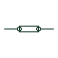
A bolted connecting link is a short removable bar between two conductors. It appears in switchboards to separate sections for testing or maintenance, as the generator neutral link, and in CT and VT circuits for isolation. The closed form shows the normal service state.
Unlike a disconnector, a link has no operating mechanism or rated breaking or making capacity. It must only be removed with the circuit dead. The symbol does not show the bolt torque or contact rating, which should match the conductor it bridges.
A bolted link is opened only when dead and with tools; a disconnector has an operating mechanism and defined isolating rating.
These public references support the explanation and provide further detail. Their graphics and downloadable files remain with their publishers.
Public directory of IEC-oriented symbol families.
Standards context for link and connection graphics.
This illustration was authored independently by Elora Grid to explain the concept. It is not reproduced from a customer drawing, an official standard graphic or a manufacturer CAD file. Its correspondence to an exact IEC or IEEE symbol identifier has not been certified.
SVG and DXF downloads contain this original artwork. DXF uses unscaled drawing units; a GA envelope supplies no product dimensions, clearances or fabrication information. Original artwork is available under CC BY 4.0. Third-party references retain their own terms.
A bolted connecting link drawn removed, showing a deliberate open point that needs tools and a dead circuit to close.
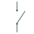
A switching device providing an electrical isolation function.
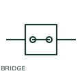
A terminal bridge intentionally connects specified terminal points to a common potential.
Elora Grid helps electrical teams work with drawings, specifications and equipment information. Explore the drafting workflow or join the early-access waitlist.