E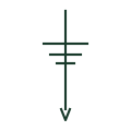
Earth electrode
A conductor in contact with the ground, such as a driven rod, providing the installation's connection to earth.
IEC
A buried horizontal earthing conductor forming part of a substation or plant earth grid, drawn on layout plans.
In plain English
Earth grid conductors are bare horizontal conductors buried under substations and plant areas to control step and touch voltages during faults. Layout drawings show them as a distinct line style, with crossings, connections to equipment and rods marked along them.
The symbol does not show conductor size, burial depth or jointing method, which come from the earthing design. A line drawn on a plan may also not indicate whether crossings are bonded; connection marks at each crossing are needed. Above-ground risers to equipment are usually shown separately.
Check crossings for bond marks. Look for risers to each equipment item. An earth grid conductor is a buried horizontal conductor; an earth electrode is a rod or plate in the soil.
A buried horizontal earthing conductor forming part of a substation or plant earth grid, drawn on layout plans. An earth grid conductor is a buried horizontal conductor; an earth electrode is a rod or plate in the soil.
Read the source: Earthing connections · Electrical installation design methodology and references

Earth grid conductors are bare horizontal conductors buried under substations and plant areas to control step and touch voltages during faults. Layout drawings show them as a distinct line style, with crossings, connections to equipment and rods marked along them.
The symbol does not show conductor size, burial depth or jointing method, which come from the earthing design. A line drawn on a plan may also not indicate whether crossings are bonded; connection marks at each crossing are needed. Above-ground risers to equipment are usually shown separately.
An earth grid conductor is a buried horizontal conductor; an earth electrode is a rod or plate in the soil.
These public references support the explanation and provide further detail. Their graphics and downloadable files remain with their publishers.
Public installation-guide earthing connection elements.
Installation design methodology references.
This illustration was authored independently by Elora Grid to explain the concept. It is not reproduced from a customer drawing, an official standard graphic or a manufacturer CAD file. Its correspondence to an exact IEC or IEEE symbol identifier has not been certified.
SVG and DXF downloads contain this original artwork. DXF uses unscaled drawing units; a GA envelope supplies no product dimensions, clearances or fabrication information. Original artwork is available under CC BY 4.0. Third-party references retain their own terms.
A conductor in contact with the ground, such as a driven rod, providing the installation's connection to earth.
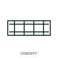
An earth bar provides a designated earthing connection point for multiple conductors.
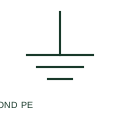
Protective equipotential bonding connects documented conductive parts as part of the protective arrangement.
Elora Grid helps electrical teams work with drawings, specifications and equipment information. Explore the drafting workflow or join the early-access waitlist.