KM
Contactor
An electrically operated switching device commonly used for repeated switching duties.
SLD / Schematic
In plain English
A charging contactor control function commands the switching device in the charging power path.
A charging controller can close the selected contactor only when the required operating conditions are satisfied.
Draw the contactor coil command separately from the main contacts carrying charging power. If the design monitors contact position, show that feedback as another signal. This makes it clear that requesting a change and confirming the physical contact state are different parts of the control sequence.
No. A command expresses the requested state. Any confirmation depends on the actual feedback arrangement and the checks implemented by the charging system.
Read the source: AC electric vehicle charging architecture
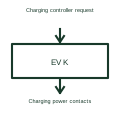
A control command does not itself verify that the contactor contacts reached the requested state.
These public references support the explanation and provide further detail. Their graphics and downloadable files remain with their publishers.
AC electric vehicle charging architecture: public technical context for the named function. Product and compliance details remain with the publisher.
This illustration was authored independently by Elora Grid to explain the concept. It is not reproduced from a customer drawing, an official standard graphic or a manufacturer CAD file. Its correspondence to an exact IEC or IEEE symbol identifier has not been certified.
SVG and DXF downloads contain this original artwork. DXF uses unscaled drawing units; a GA envelope supplies no product dimensions, clearances or fabrication information. Original artwork is available under CC BY 4.0. Third-party references retain their own terms.
An electrically operated switching device commonly used for repeated switching duties.
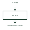
An AC charge point controls the AC supply and charging interface presented to a vehicle.
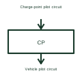
The control pilot is part of the signalling interface between charging equipment and a vehicle.
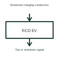
Residual-current detection checks for specified unintended current paths in a charging system.
Elora Grid helps electrical teams work with drawings, specifications and equipment information. Explore the drafting workflow or join the early-access waitlist.