RMU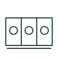
Ring main unit
A secondary-distribution switchgear assembly with a selected combination of switching functions.
GA objects
Device on an MV cable or overhead feeder that shows whether fault current has passed its location, to speed fault finding.
In plain English
A fault passage indicator senses current at a point on a medium-voltage feeder and shows, with a flag or LED, when fault current has passed. Operators follow the indicators along a feeder to find the faulted section between the last operated indicator and the first unoperated one.
Indicators may sense phase faults, earth faults or both, and many can signal remotely to SCADA. The symbol does not show the sensing method, reset method or thresholds, which must suit the network earthing and feeder load to avoid false or missed indications.
Check whether the indicator covers phase faults, earth faults or both. Note any remote signalling output. A fault passage indicator only signals; a protection relay trips a breaker.
Device on an MV cable or overhead feeder that shows whether fault current has passed its location, to speed fault finding. A fault passage indicator only signals; a protection relay trips a breaker.
Read the source: Secondary-distribution switchgear and ring main units
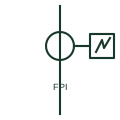
A fault passage indicator senses current at a point on a medium-voltage feeder and shows, with a flag or LED, when fault current has passed. Operators follow the indicators along a feeder to find the faulted section between the last operated indicator and the first unoperated one.
Indicators may sense phase faults, earth faults or both, and many can signal remotely to SCADA. The symbol does not show the sensing method, reset method or thresholds, which must suit the network earthing and feeder load to avoid false or missed indications.
A fault passage indicator only signals; a protection relay trips a breaker.
These public references support the explanation and provide further detail. Their graphics and downloadable files remain with their publishers.
Public secondary-distribution switchgear and ring main unit context where fault indicators are fitted.
This illustration was authored independently by Elora Grid to explain the concept. It is not reproduced from a customer drawing, an official standard graphic or a manufacturer CAD file. Its correspondence to an exact IEC or IEEE symbol identifier has not been certified.
SVG and DXF downloads contain this original artwork. DXF uses unscaled drawing units; a GA envelope supplies no product dimensions, clearances or fabrication information. Original artwork is available under CC BY 4.0. Third-party references retain their own terms.
A secondary-distribution switchgear assembly with a selected combination of switching functions.
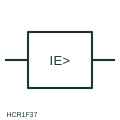
Measuring relay form that operates on current flowing to earth, fed from a residual connection or core-balance CT.

A core-balance CT measures residual current from the net magnetic effect of conductors passing through its window.
Elora Grid helps electrical teams work with drawings, specifications and equipment information. Explore the drafting workflow or join the early-access waitlist.