DG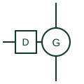
Diesel generator set
A compression-ignition engine coupled to an alternator, shown as a source on microgrid and standby power single-line diagrams.
SLD
The device controller that starts, protects and synchronises a generating set and controls its breaker.
In plain English
A genset controller starts and stops the engine, monitors engine sensors, provides generator protection functions and, in paralleling versions, synchronises the set and shares load with other sources. Automatic mains failure versions also monitor the utility supply and control the changeover.
Single-line diagrams draw it as a block beside the generator with measurement inputs from generator CTs and VTs, a breaker close and trip connection and a communication link to the microgrid or power management controller. The protection functions it provides are often listed by device number.
The block does not tell you whether it provides certified utility interface protection or only generator protection. It also does not show the governor and regulator interface, which may be analogue, digital or a communication link to the engine control unit.
The device controller that starts, protects and synchronises a generating set and controls its breaker. A genset controller handles one set; a microgrid controller coordinates many sources.
Read the source: Single genset controllers for backup power · iE 250 controller documentation
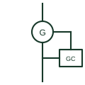
A genset controller starts and stops the engine, monitors engine sensors, provides generator protection functions and, in paralleling versions, synchronises the set and shares load with other sources. Automatic mains failure versions also monitor the utility supply and control the changeover.
Single-line diagrams draw it as a block beside the generator with measurement inputs from generator CTs and VTs, a breaker close and trip connection and a communication link to the microgrid or power management controller. The protection functions it provides are often listed by device number.
The block does not tell you whether it provides certified utility interface protection or only generator protection. It also does not show the governor and regulator interface, which may be analogue, digital or a communication link to the engine control unit.
A genset controller handles one set; a microgrid controller coordinates many sources.
These public references support the explanation and provide further detail. Their graphics and downloadable files remain with their publishers.
Public single genset controller page describing start, stop and protection functions.
Public controller documentation.
This illustration was authored independently by Elora Grid to explain the concept. It is not reproduced from a customer drawing, an official standard graphic or a manufacturer CAD file. Its correspondence to an exact IEC or IEEE symbol identifier has not been certified.
SVG and DXF downloads contain this original artwork. DXF uses unscaled drawing units; a GA envelope supplies no product dimensions, clearances or fabrication information. Original artwork is available under CC BY 4.0. Third-party references retain their own terms.
A compression-ignition engine coupled to an alternator, shown as a source on microgrid and standby power single-line diagrams.
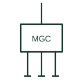
The supervisory controller that dispatches sources, storage and loads and manages islanding and reconnection of a microgrid.

A paralleling controller coordinates specified generator and switching functions.

Checks documented synchronising conditions before a permitted connection.
Elora Grid helps electrical teams work with drawings, specifications and equipment information. Explore the drafting workflow or join the early-access waitlist.