TEMP TX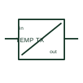
Temperature measuring transducer
A temperature transducer converts a documented temperature-sensor input into an instrument signal.
SLD / Schematic
In plain English
A Hall-effect current sensor uses a magnetic-field response to measure current.
An appropriately selected sensor can report current in a battery or power-conversion circuit.
Identify the current-carrying conductor and the sensor’s signal output separately. Hall sensing uses the conductor’s magnetic field to obtain current information. Unlike a conventional AC current transformer, a suitable Hall-based sensor can be selected for measurements involving DC; its actual range and isolation remain product-specific.
No. The sensing principle differs. A conventional current transformer and a Hall-based sensor have different capabilities and limitations, so their interfaces and operating conditions must be checked separately.
Read the source: Hall-effect current-sensing example
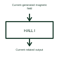
Hall sensing and a conventional AC current transformer have different operating principles and limits.
These public references support the explanation and provide further detail. Their graphics and downloadable files remain with their publishers.
Primary-source technical context for this particular function; product-specific ratings remain with the manufacturer.
This illustration was authored independently by Elora Grid to explain the concept. It is not reproduced from a customer drawing, an official standard graphic or a manufacturer CAD file. Its correspondence to an exact IEC or IEEE symbol identifier has not been certified.
SVG and DXF downloads contain this original artwork. DXF uses unscaled drawing units; a GA envelope supplies no product dimensions, clearances or fabrication information. Original artwork is available under CC BY 4.0. Third-party references retain their own terms.
A temperature transducer converts a documented temperature-sensor input into an instrument signal.
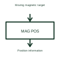
A magnetic position sensor measures or detects position through the magnetic field associated with a target.
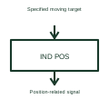
An inductive position sensor uses an electromagnetic interaction to infer a target's position.
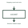
An ultrasonic distance sensor uses sound beyond normal human hearing to obtain distance information.
Elora Grid helps electrical teams work with drawings, specifications and equipment information. Explore the drafting workflow or join the early-access waitlist.