CLK-GEN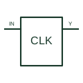
Clock generator
Provides the documented clock signal or signals used by digital circuitry.
Schematic
IEC element marked G, an astable that produces a continuous pulse train; drawing the waveform is optional.
In plain English
The astable element is marked with G, optionally followed by a sketch of the output waveform. It produces a free-running pulse train. Variants include !G for a synchronously starting astable and G! for one that stops only after completing a pulse, as listed in TI's public overview.
Astable elements represent oscillators on logic diagrams: flasher circuits for indicator lamps, test pulse generators and clock sources. Where an enable input exists, its effect on the output at start and stop should be considered because the variant qualifiers describe exactly that.
The symbol does not state frequency or duty cycle. Note those values beside the element or reference the timing components.
IEC element marked G, an astable that produces a continuous pulse train; drawing the waveform is optional. A monostable produces one pulse per trigger; an astable runs continuously while enabled.
Read the source: Overview of IEEE Standard 91-1984: explanation of logic symbols (SDYZ001A)
Qualifying-symbol and dependency conventions as explained in TI's public overview of IEEE Std 91-1984, which incorporates IEC 617-12 work. Independent educational drawing; not certified IEC geometry or an IEC database identifier.
Shown as an independently authored educational illustration. Use the cited publication and drawing legend to verify the required drafting form.
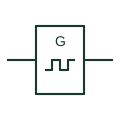
The astable element is marked with G, optionally followed by a sketch of the output waveform. It produces a free-running pulse train. Variants include !G for a synchronously starting astable and G! for one that stops only after completing a pulse, as listed in TI's public overview.
Astable elements represent oscillators on logic diagrams: flasher circuits for indicator lamps, test pulse generators and clock sources. Where an enable input exists, its effect on the output at start and stop should be considered because the variant qualifiers describe exactly that.
The symbol does not state frequency or duty cycle. Note those values beside the element or reference the timing components.
A monostable produces one pulse per trigger; an astable runs continuously while enabled.
These public references support the explanation and provide further detail. Their graphics and downloadable files remain with their publishers.
Lists G, !G and G! astable qualifiers.
This illustration was authored independently by Elora Grid to explain the concept. It is not reproduced from a customer drawing, an official standard graphic or a manufacturer CAD file. Its correspondence to an exact IEC or IEEE symbol identifier has not been certified.
SVG and DXF downloads contain this original artwork. DXF uses unscaled drawing units; a GA envelope supplies no product dimensions, clearances or fabrication information. Original artwork is available under CC BY 4.0. Third-party references retain their own terms.
Provides the documented clock signal or signals used by digital circuitry.
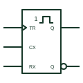
IEC monostable marked with 1 and a single pulse: a trigger during the output pulse is ignored.
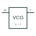
Generates an oscillating output whose frequency responds to the documented control voltage.
Elora Grid helps electrical teams work with drawings, specifications and equipment information. Explore the drafting workflow or join the early-access waitlist.