D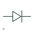
Diode
A diode provides a semiconductor path with documented directional conduction characteristics.
Schematic
Backward diode form: Backward (Unitunnel) Diode.
In plain English
A backward diode uses tunnelling behaviour to provide useful conduction at a small reverse bias. Its operating region is different from the forward-conduction region of an ordinary rectifier. This entry identifies the backward (unitunnel) diode form in the publisher's IEC-context family.
A small-signal detector can exploit the low-bias response. Trace the bias and signal polarity in the complete circuit rather than treating the device as a reverse-polarity protection rectifier.
A backward diode is related to tunnel-device physics; it is not simply an ordinary diode drawn in the opposite direction.
Backward diode form: Backward (Unitunnel) Diode. This entry adds the backward (unitunnel) diode detail to the broader backward diode family. A backward diode is related to tunnel-device physics; it is not simply an ordinary diode drawn in the opposite direction.
Read the source: AutoCAD Electrical: Semiconductor components
Autodesk IEC-60617 Symbol Preview: Semiconductor Components, HDI1_S00648 / VDI1_S00648. This identifies the publisher's library context; exact IEC graphics and database identities are not asserted.
Shown as an independently authored educational illustration. Use the cited publication and drawing legend to verify the required drafting form.
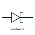
A backward diode uses tunnelling behaviour to provide useful conduction at a small reverse bias. Its operating region is different from the forward-conduction region of an ordinary rectifier. This entry identifies the backward (unitunnel) diode form in the publisher's IEC-context family.
A small-signal detector can exploit the low-bias response. Trace the bias and signal polarity in the complete circuit rather than treating the device as a reverse-polarity protection rectifier.
A backward diode is related to tunnel-device physics; it is not simply an ordinary diode drawn in the opposite direction.
This entry adds the backward (unitunnel) diode detail to the broader backward diode family. A backward diode is related to tunnel-device physics; it is not simply an ordinary diode drawn in the opposite direction.
These public references support the explanation and provide further detail. Their graphics and downloadable files remain with their publishers.
Public Semiconductor Components table explicitly lists HDI1_S00648 / VDI1_S00648 with this operating or connection form. Vendor graphics are linked, not copied.
This illustration was authored independently by Elora Grid to explain the concept. It is not reproduced from a customer drawing, an official standard graphic or a manufacturer CAD file. Its correspondence to an exact IEC or IEEE symbol identifier has not been certified.
SVG and DXF downloads contain this original artwork. DXF uses unscaled drawing units; a GA envelope supplies no product dimensions, clearances or fabrication information. Original artwork is available under CC BY 4.0. Third-party references retain their own terms.
A diode provides a semiconductor path with documented directional conduction characteristics.
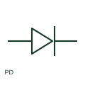
A photodiode is a light-sensitive semiconductor device used in a documented sensing circuit.
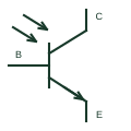
An NPN transistor whose collector-emitter conduction responds to incident light in the documented detector arrangement.
Elora Grid helps electrical teams work with drawings, specifications and equipment information. Explore the drafting workflow or join the early-access waitlist.