PULL CORD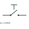
Pull-cord switch
A pull-cord switch converts a cord-operated mechanical action into an electrical contact change.
Schematic
Plan mark for a ceiling-mounted switch operated by a hanging cord, common in bathrooms and accessible toilets.
In plain English
A ceiling pull-cord switch is a one-way or two-pole switch fixed to the ceiling and operated by a cord. The plan mark adds a short line with a small arrow or cord end to the switch symbol, telling the reader that the device sits at ceiling level and is operated from below.
These switches are used in bathrooms where a wall switch would be in a restricted zone, and in accessible toilets where the cord forms part of an assistance call system. The plan should distinguish a light-switching pull cord from an emergency assistance pull cord, which is a different device.
The plan mark does not give the cord length or ceiling fixing detail. Those come from the specification and accessibility requirements.
Plan mark for a ceiling-mounted switch operated by a hanging cord, common in bathrooms and accessible toilets. The schematic pull-cord switch in control circuits is a machine emergency device; this plan mark is a building lighting accessory.
Read the source: IEC graphical symbols for diagrams · Autodesk IEC-60617 preview: Operating-device and function qualifiers
IEC 60617 installation-plan style (architectural and topographical installation symbols); independently drawn, not certified IEC geometry or a database identifier.
Shown as an independently authored educational illustration. Use the cited publication and drawing legend to verify the required drafting form.

A ceiling pull-cord switch is a one-way or two-pole switch fixed to the ceiling and operated by a cord. The plan mark adds a short line with a small arrow or cord end to the switch symbol, telling the reader that the device sits at ceiling level and is operated from below.
These switches are used in bathrooms where a wall switch would be in a restricted zone, and in accessible toilets where the cord forms part of an assistance call system. The plan should distinguish a light-switching pull cord from an emergency assistance pull cord, which is a different device.
The plan mark does not give the cord length or ceiling fixing detail. Those come from the specification and accessibility requirements.
The schematic pull-cord switch in control circuits is a machine emergency device; this plan mark is a building lighting accessory.
These public references support the explanation and provide further detail. Their graphics and downloadable files remain with their publishers.
IEC graphical symbol context; independently drawn here.
Public IEC-oriented family showing operating-device qualifiers such as pull operation.
This illustration was authored independently by Elora Grid to explain the concept. It is not reproduced from a customer drawing, an official standard graphic or a manufacturer CAD file. Its correspondence to an exact IEC or IEEE symbol identifier has not been certified.
SVG and DXF downloads contain this original artwork. DXF uses unscaled drawing units; a GA envelope supplies no product dimensions, clearances or fabrication information. Original artwork is available under CC BY 4.0. Third-party references retain their own terms.
Elora Grid helps electrical teams work with drawings, specifications and equipment information. Explore the drafting workflow or join the early-access waitlist.