GA
Fibre-optic patch panel
A fibre patch panel organises optical terminations and patch connections.
GA objects
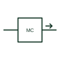
Symbol for an optical fibre link between devices, a line with a fibre mark, often with media converters at each end.
In plain English
Fibre-optic links are drawn as a line carrying a fibre indication, such as a small loop, a wavy section or the tag FO, between the devices they connect. Network diagrams also show the fibre count and type, such as 12-core single-mode.
Electrical drawings use fibre links for substation communications, between buildings and through areas with electrical noise or earth potential rise, because fibre gives electrical separation without a direct conducting path. The symbol is often terminated in a media converter or switch fibre port. The symbol does not specify connectors, loss budget or route. The fibre schedule and test results cover these.
Read core count and fibre type. Find the termination at each end. A copper data cable has no isolation benefit; the fibre link isolates the two ends electrically.
Symbol for an optical fibre link between devices, a line with a fibre mark, often with media converters at each end. A copper data cable has no isolation benefit; the fibre link isolates the two ends electrically.
Read the source: IEC graphical symbols for diagrams · Industrial Ethernet to fibre media converters · Autodesk IEC-60617 preview: Propagation and signal-flow qualifiers
IEC 60617 installation-plan style (architectural and topographical installation symbols); independently drawn, not certified IEC geometry or a database identifier.
Shown as an independently authored educational illustration. Use the cited publication and drawing legend to verify the required drafting form.
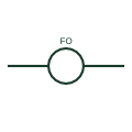
Fibre-optic links are drawn as a line carrying a fibre indication, such as a small loop, a wavy section or the tag FO, between the devices they connect. Network diagrams also show the fibre count and type, such as 12-core single-mode.
Electrical drawings use fibre links for substation communications, between buildings and through areas with electrical noise or earth potential rise, because fibre gives galvanic isolation. The symbol is often terminated in a media converter or switch fibre port. The symbol does not specify connectors, loss budget or route. The fibre schedule and test results cover these.
A copper data cable has no isolation benefit; the fibre link isolates the two ends electrically.
These public references support the explanation and provide further detail. Their graphics and downloadable files remain with their publishers.
IEC graphical symbol context for installation and communication plans; independently drawn here.
Public product family page describing copper Ethernet to fibre conversion.
Public IEC-oriented propagation and signal-flow qualifiers used on communication symbols.
This illustration was authored independently by Elora Grid to explain the concept. It is not reproduced from a customer drawing, an official standard graphic or a manufacturer CAD file. Its correspondence to an exact IEC or IEEE symbol identifier has not been certified.
SVG and DXF downloads contain this original artwork. DXF uses unscaled drawing units; a GA envelope supplies no product dimensions, clearances or fabrication information. Original artwork is available under CC BY 4.0. Third-party references retain their own terms.
Elora Grid helps electrical teams work with drawings, specifications and equipment information. Explore the drafting workflow or join the early-access waitlist.