SD
Smoke detector plan symbol
Fire alarm plan symbol for a point smoke detector, drawn as a detector box with a smoke indication.
IEC
Plan symbol for a flame detector that senses ultraviolet or infrared radiation from flames, with its cone of view.
In plain English
Flame detectors sense the radiation emitted by flames, using ultraviolet, infrared or combined sensors. Plans draw the detector with radiation arrows and often the field-of-view cone so coverage can be checked against the protected hazard.
They are used for fuel stores, generator rooms, turbine enclosures and hazardous industrial areas where flaming fires are expected. Hazardous-area classification may also apply to the device, which the plan should tag. The cone drawn is approximate; sensitivity falls with distance and angle. Check the product data.
Check the cone covers the hazard. Check hazardous-area markings. A smoke detector responds to particles; a flame detector responds to radiation from the flame.
Plan symbol for a flame detector that senses ultraviolet or infrared radiation from flames, with its cone of view. A smoke detector responds to particles; a flame detector responds to radiation from the flame.
Read the source: IEC graphical symbols for diagrams · Autodesk IEC-60617 preview: Radiation qualifiers
IEC 60617 installation-plan style (architectural and topographical installation symbols); independently drawn, not certified IEC geometry or a database identifier.
Shown as an independently authored educational illustration. Use the cited publication and drawing legend to verify the required drafting form.
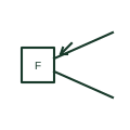
Flame detectors sense the radiation emitted by flames, using ultraviolet, infrared or combined sensors. Plans draw the detector with radiation arrows and often the field-of-view cone so coverage can be checked against the protected hazard.
They are used for fuel stores, generator rooms, turbine enclosures and hazardous industrial areas where flaming fires are expected. Hazardous-area classification may also apply to the device, which the plan should tag. The cone drawn is approximate; sensitivity falls with distance and angle. Check the product data.
A smoke detector responds to particles; a flame detector responds to radiation from the flame.
These public references support the explanation and provide further detail. Their graphics and downloadable files remain with their publishers.
IEC graphical symbol context for installation plans; independently drawn here.
Public IEC-oriented radiation qualifiers relevant to optical and infrared detection marks.
This illustration was authored independently by Elora Grid to explain the concept. It is not reproduced from a customer drawing, an official standard graphic or a manufacturer CAD file. Its correspondence to an exact IEC or IEEE symbol identifier has not been certified.
SVG and DXF downloads contain this original artwork. DXF uses unscaled drawing units; a GA envelope supplies no product dimensions, clearances or fabrication information. Original artwork is available under CC BY 4.0. Third-party references retain their own terms.
Fire alarm plan symbol for a point smoke detector, drawn as a detector box with a smoke indication.
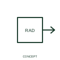
This qualifier identifies the publisher's non-ionising radiation family, with the radiation role stated in the device description.
Elora Grid helps electrical teams work with drawings, specifications and equipment information. Explore the drafting workflow or join the early-access waitlist.