-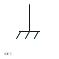
ANSI/IEEE chassis ground symbol
IEEE-oriented chassis or frame ground drawn as a line ending in angled strokes, used for equipment frame returns.
IEEE / ANSI
A connection to the metal frame or chassis of equipment, which may or may not itself be connected to earth.
In plain English
The frame or chassis connection shows that a circuit point is connected to the metal structure of a device, drawn as a line ending in a comb or hatched mark. It is common on electronics, vehicle and machine wiring, where the chassis is used as a common reference or return.
A chassis connection is not automatically an earth connection. Equipment on a vehicle or isolated supply may have a chassis that is not connected to earth at all. Where the chassis is also protectively earthed, the protective earth symbol should be shown separately so the safety function is clear.
Do not assume the chassis is earthed. Look for a separate protective earth connection on the frame. A chassis connection ties to the equipment frame; a protective earth connection ties to the installation earthing system.
A connection to the metal frame or chassis of equipment, which may or may not itself be connected to earth. A chassis connection ties to the equipment frame; a protective earth connection ties to the installation earthing system.
Read the source: AutoCAD Electrical: Earthing, sources and surge protection · IEC-60617 symbol preview directory
Independent IEC-context illustration; not certified IEC geometry.
Shown as an independently authored educational illustration. Use the cited publication and drawing legend to verify the required drafting form.
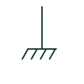
The frame or chassis connection shows that a circuit point is connected to the metal structure of a device, drawn as a line ending in a comb or hatched mark. It is common on electronics, vehicle and machine wiring, where the chassis is used as a common reference or return.
A chassis connection is not automatically an earth connection. Equipment on a vehicle or isolated supply may have a chassis that is not connected to earth at all. Where the chassis is also protectively earthed, the protective earth symbol should be shown separately so the safety function is clear.
A chassis connection ties to the equipment frame; a protective earth connection ties to the installation earthing system.
These public references support the explanation and provide further detail. Their graphics and downloadable files remain with their publishers.
Public IEC-oriented earth and bonding forms.
Public directory of IEC-oriented symbol families.
This illustration was authored independently by Elora Grid to explain the concept. It is not reproduced from a customer drawing, an official standard graphic or a manufacturer CAD file. Its correspondence to an exact IEC or IEEE symbol identifier has not been certified.
SVG and DXF downloads contain this original artwork. DXF uses unscaled drawing units; a GA envelope supplies no product dimensions, clearances or fabrication information. Original artwork is available under CC BY 4.0. Third-party references retain their own terms.
IEEE-oriented chassis or frame ground drawn as a line ending in angled strokes, used for equipment frame returns.

An identified connection serving the protective earthing function.
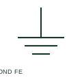
Functional equipotential bonding connects documented points for an operational or signal-related purpose.
Elora Grid helps electrical teams work with drawings, specifications and equipment information. Explore the drafting workflow or join the early-access waitlist.