JUNCTION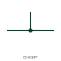
Conductor connection junction
A junction indication marks a documented electrical connection between conductor branches.
Schematic
Plan mark for a junction or joint box where installation cables are connected or branched.
In plain English
A junction box mark shows where cables are joined in an enclosure, commonly in ceiling voids for lighting circuits or above ceilings for equipment connections. Plans draw a small circle or square with a dot, sometimes labelled JB, at the location.
Access matters: joints must remain accessible for inspection unless a maintenance-free method is used, so the plan should not place a junction box above a fixed plasterboard ceiling without an access panel. The symbol helps coordinate this with architectural trades.
The mark does not show the number of terminals or cables. A junction box serving fixed equipment may also be a final connection point; check the schedule.
Plan mark for a junction or joint box where installation cables are connected or branched. A conductor junction dot on a schematic shows electrical connection; this plan mark shows a physical box.
Read the source: IEC graphical symbols for diagrams
IEC 60617 installation-plan style (architectural and topographical installation symbols); independently drawn, not certified IEC geometry or a database identifier.
Shown as an independently authored educational illustration. Use the cited publication and drawing legend to verify the required drafting form.
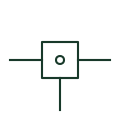
A junction box mark shows where cables are joined in an enclosure, commonly in ceiling voids for lighting circuits or above ceilings for equipment connections. Plans draw a small circle or square with a dot, sometimes labelled JB, at the location.
Access matters: joints must remain accessible for inspection unless a maintenance-free method is used, so the plan should not place a junction box above a fixed plasterboard ceiling without an access panel. The symbol helps coordinate this with architectural trades.
The mark does not show the number of terminals or cables. A junction box serving fixed equipment may also be a final connection point; check the schedule.
A conductor junction dot on a schematic shows electrical connection; this plan mark shows a physical box.
These public references support the explanation and provide further detail. Their graphics and downloadable files remain with their publishers.
IEC graphical symbol context; independently drawn here.
This illustration was authored independently by Elora Grid to explain the concept. It is not reproduced from a customer drawing, an official standard graphic or a manufacturer CAD file. Its correspondence to an exact IEC or IEEE symbol identifier has not been certified.
SVG and DXF downloads contain this original artwork. DXF uses unscaled drawing units; a GA envelope supplies no product dimensions, clearances or fabrication information. Original artwork is available under CC BY 4.0. Third-party references retain their own terms.
Elora Grid helps electrical teams work with drawings, specifications and equipment information. Explore the drafting workflow or join the early-access waitlist.