E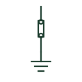
Removable earth test link
A removable link between the main earthing terminal and the earth electrode, opened to measure electrode resistance.
IEC
The terminal or bar where protective conductors, bonding conductors and the earthing conductor of an installation meet.
In plain English
The main earthing terminal is the hub of an installation's earthing. Installation guidance describes it as the point that provides the main equipotential connection, with the earthing conductor to the electrode, main bonding conductors to metallic services and protective conductors to circuits all landed on it. Earthing schematics draw it as a bar with labelled connections.
The symbol shows the hub but not the size of each conductor, which must be scheduled. It also does not show the removable test link, which should be drawn on the electrode connection. In larger sites, sub-main earth bars are separate items connected back to the MET.
Check that every main bonding conductor lands on the MET. Look for the test link on the electrode conductor. The main earthing terminal is the installation's earthing hub; a protective-earth terminal block is a single terminal in a panel.
The terminal or bar where protective conductors, bonding conductors and the earthing conductor of an installation meet. The main earthing terminal is the installation's earthing hub; a protective-earth terminal block is a single terminal in a panel.
Read the source: Earthing connections · AutoCAD Electrical: Earthing, sources and surge protection
Independent IEC-context illustration; not certified IEC geometry.
Shown as an independently authored educational illustration. Use the cited publication and drawing legend to verify the required drafting form.
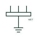
The main earthing terminal is the hub of an installation's earthing. Installation guidance describes it as the point that provides the main equipotential connection, with the earthing conductor to the electrode, main bonding conductors to metallic services and protective conductors to circuits all landed on it. Earthing schematics draw it as a bar with labelled connections.
The symbol shows the hub but not the size of each conductor, which must be scheduled. It also does not show the removable test link, which should be drawn on the electrode connection. In larger sites, sub-main earth bars are separate items connected back to the MET.
The main earthing terminal is the installation's earthing hub; a protective-earth terminal block is a single terminal in a panel.
These public references support the explanation and provide further detail. Their graphics and downloadable files remain with their publishers.
Public installation-guide definition of the main earthing terminal.
Public IEC-oriented earth and bonding forms.
This illustration was authored independently by Elora Grid to explain the concept. It is not reproduced from a customer drawing, an official standard graphic or a manufacturer CAD file. Its correspondence to an exact IEC or IEEE symbol identifier has not been certified.
SVG and DXF downloads contain this original artwork. DXF uses unscaled drawing units; a GA envelope supplies no product dimensions, clearances or fabrication information. Original artwork is available under CC BY 4.0. Third-party references retain their own terms.
A removable link between the main earthing terminal and the earth electrode, opened to measure electrode resistance.
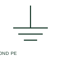
Protective equipotential bonding connects documented conductive parts as part of the protective arrangement.
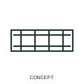
An earth bar provides a designated earthing connection point for multiple conductors.
Elora Grid helps electrical teams work with drawings, specifications and equipment information. Explore the drafting workflow or join the early-access waitlist.