PLUG SOCKET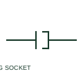
Plug and socket connector pair
A plug/socket pair represents a detachable electrical connection with two mating sides.
Schematic
A plug and socket pair drawn with several poles side by side, showing a multi-way connector carrying several conductors.
In plain English
The multi-pole form draws each contact of a connector as a pin and socket pair, grouped together and tied by a common outline or mechanical link to show they belong to one connector body. It is used for machine harness connectors, removable control modules and multi-pin field connectors on instruments.
The multi-line form shows every pin, which makes it suitable for wiring diagrams where pin numbers matter. It does not show keying, coding or the connector series, which prevent mismating and must be stated in text. Unused pins are often omitted, so the pin count drawn may be less than the connector size.
Match pin numbers on the drawing to the connector insert layout. Check whether unused pins are omitted. A multi-pole plug and socket draws each pin; the one-line connector representation shows the whole connector as one mark.
A plug and socket pair drawn with several poles side by side, showing a multi-way connector carrying several conductors. A multi-pole plug and socket draws each pin; the one-line connector representation shows the whole connector as one mark.
Read the source: AutoCAD Electrical: Connectors · IEC-60617 symbol preview directory
Autodesk IEC-60617 Symbol Preview: Connectors - No Wirenumber Changes; vendor family reference, not certified IEC geometry.
Shown as an independently authored educational illustration. Use the cited publication and drawing legend to verify the required drafting form.
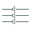
The multi-pole form draws each contact of a connector as a pin and socket pair, grouped together and tied by a common outline or mechanical link to show they belong to one connector body. It is used for machine harness connectors, removable control modules and multi-pin field connectors on instruments.
The multi-line form shows every pin, which makes it suitable for wiring diagrams where pin numbers matter. It does not show keying, coding or the connector series, which prevent mismating and must be stated in text. Unused pins are often omitted, so the pin count drawn may be less than the connector size.
A multi-pole plug and socket draws each pin; the one-line connector representation shows the whole connector as one mark.
These public references support the explanation and provide further detail. Their graphics and downloadable files remain with their publishers.
Public IEC-oriented preview of plug and jack connector forms.
Public directory of IEC-oriented symbol families.
This illustration was authored independently by Elora Grid to explain the concept. It is not reproduced from a customer drawing, an official standard graphic or a manufacturer CAD file. Its correspondence to an exact IEC or IEEE symbol identifier has not been certified.
SVG and DXF downloads contain this original artwork. DXF uses unscaled drawing units; a GA envelope supplies no product dimensions, clearances or fabrication information. Original artwork is available under CC BY 4.0. Third-party references retain their own terms.
A plug/socket pair represents a detachable electrical connection with two mating sides.
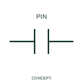
A one-line connector representation identifies a connector interface in a simplified circuit view.
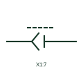
A further pin of a connector already tagged elsewhere, drawn without repeating the connector body or tag.
Elora Grid helps electrical teams work with drawings, specifications and equipment information. Explore the drafting workflow or join the early-access waitlist.