PHOTO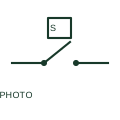
Photoelectric emitter-receiver switch
A photoelectric emitter-receiver device uses an optical path to determine a switching output.
Schematic
Photoelectric receiver form: Normally Open Receiver 3 wire with connector.
In plain English
A photoelectric receiver evaluates light arriving from an associated emitter and provides the documented electrical response. This entry identifies the normally open receiver 3 wire with connector form in the publisher's IEC-context family.
An object crossing a conveyor beam can change the receiver output. The receiver tag should identify its optical partner and the controller input receiving its signal. The normally-open designation starts with a non-conducting output or open contact in the documented reference condition; operation changes that state. The three-wire form distinguishes supply, return and switching output. Confirm sourcing or sinking operation from the actual sensor circuit before connecting it to an input.
The connector variant adds a separable field interface. Keep the mating connector designation, pin numbers and cable-core mapping visible at that boundary. Normally-open and normally-closed labels describe the documented electrical output form. They do not by themselves establish light-on or dark-on operation; confirm that setting with the device data.
Photoelectric receiver form: Normally Open Receiver 3 wire with connector. This entry adds the normally open receiver 3 wire with connector detail to the broader photoelectric receiver family. Normally-open and normally-closed labels describe the documented electrical output form. They do not by themselves establish light-on or dark-on operation; confirm that setting with the device data.
Read the source: Autodesk IEC-60617 Symbol Preview: Photoelectric Receiver Switches
Autodesk IEC-60617 Symbol Preview: Photoelectric Receiver Switches, HPE11PE3C / VPE11PE3C. This identifies the publisher's library context; exact IEC graphics and database identities are not asserted.
Shown as an independently authored educational illustration. Use the cited publication and drawing legend to verify the required drafting form.
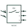
A photoelectric receiver evaluates light arriving from an associated emitter and provides the documented electrical response. This entry identifies the normally open receiver 3 wire with connector form in the publisher's IEC-context family.
An object crossing a conveyor beam can change the receiver output. The receiver tag should identify its optical partner and the controller input receiving its signal. The normally-open designation starts with a non-conducting output or open contact in the documented reference condition; operation changes that state. The three-wire form distinguishes supply, return and switching output. Confirm sourcing or sinking operation from the actual sensor circuit before connecting it to an input.
The connector variant adds a separable field interface. Keep the mating connector designation, pin numbers and cable-core mapping visible at that boundary. Normally-open and normally-closed labels describe the documented electrical output form. They do not by themselves establish light-on or dark-on operation; confirm that setting with the device data.
This entry adds the normally open receiver 3 wire with connector detail to the broader photoelectric receiver family. Normally-open and normally-closed labels describe the documented electrical output form. They do not by themselves establish light-on or dark-on operation; confirm that setting with the device data.
These public references support the explanation and provide further detail. Their graphics and downloadable files remain with their publishers.
Public Photoelectric Receiver Switches table explicitly lists HPE11PE3C / VPE11PE3C with this operating or connection form. Vendor graphics are linked, not copied.
This illustration was authored independently by Elora Grid to explain the concept. It is not reproduced from a customer drawing, an official standard graphic or a manufacturer CAD file. Its correspondence to an exact IEC or IEEE symbol identifier has not been certified.
SVG and DXF downloads contain this original artwork. DXF uses unscaled drawing units; a GA envelope supplies no product dimensions, clearances or fabrication information. Original artwork is available under CC BY 4.0. Third-party references retain their own terms.
A photoelectric emitter-receiver device uses an optical path to determine a switching output.
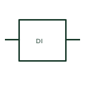
A PLC digital input reads a documented discrete electrical state from field wiring.

An identified electrical connection point linking schematic and wiring information.
Elora Grid helps electrical teams work with drawings, specifications and equipment information. Explore the drafting workflow or join the early-access waitlist.