RCCB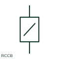
Residual-current circuit breaker
An RCCB operates on residual current and has no integral overcurrent protection.
SLD / Schematic
Plan mark for a socket outlet with residual-current protection built into the accessory itself.
In plain English
Some outlets include a residual-current device in the accessory so that protection is provided at the point of use. Plans show this by tagging the outlet with RCD or a small residual-current mark, letting the electrician select a protected accessory instead of relying on the distribution board.
This approach is used for single outdoor outlets, refurbishment work where the board cannot take additional RCDs, and outlets used for portable tools. The plan symbol should be read with the board schedule so the designer can avoid double protection or check discrimination between the outlet RCD and an upstream device.
The mark does not state the RCD type, rated residual current or test arrangement. A plain outlet on an RCD-protected circuit is protected at the board and is drawn without this tag.
Plan mark for a socket outlet with residual-current protection built into the accessory itself. An outlet on a circuit protected by a residual-current circuit breaker is drawn plainly; this form puts the RCD in the outlet.
Read the source: Form factors of residual-current devices · Residual current device categories · IEC graphical symbols for diagrams
IEC 60617 installation-plan style (architectural and topographical installation symbols); independently drawn, not certified IEC geometry or a database identifier.
Shown as an independently authored educational illustration. Use the cited publication and drawing legend to verify the required drafting form.
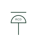
Some outlets include a residual-current device in the accessory so that protection is provided at the point of use. Plans show this by tagging the outlet with RCD or a small residual-current mark, letting the electrician select a protected accessory instead of relying on the distribution board.
This approach is used for single outdoor outlets, refurbishment work where the board cannot take additional RCDs, and outlets used for portable tools. The plan symbol should be read with the board schedule so the designer can avoid double protection or check discrimination between the outlet RCD and an upstream device.
The mark does not state the RCD type, rated residual current or test arrangement. A plain outlet on an RCD-protected circuit is protected at the board and is drawn without this tag.
An outlet on a circuit protected by a residual-current circuit breaker is drawn plainly; this form puts the RCD in the outlet.
These public references support the explanation and provide further detail. Their graphics and downloadable files remain with their publishers.
Explains the physical forms residual-current protection can take, including socket-outlet integration.
Manufacturer explanation of residual-current device types and categories.
IEC committee context for graphical symbols used in diagrams and installation documents; not a source of reproduced artwork.
This illustration was authored independently by Elora Grid to explain the concept. It is not reproduced from a customer drawing, an official standard graphic or a manufacturer CAD file. Its correspondence to an exact IEC or IEEE symbol identifier has not been certified.
SVG and DXF downloads contain this original artwork. DXF uses unscaled drawing units; a GA envelope supplies no product dimensions, clearances or fabrication information. Original artwork is available under CC BY 4.0. Third-party references retain their own terms.
An RCCB operates on residual current and has no integral overcurrent protection.

Plan mark for an outdoor or wet-area socket outlet with a protective enclosure, usually tagged with its IP rating.

US plan symbol for a duplex receptacle with built-in ground-fault circuit-interrupter protection, tagged GFCI.
Elora Grid helps electrical teams work with drawings, specifications and equipment information. Explore the drafting workflow or join the early-access waitlist.