TON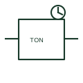
On-delay timer relay
An on-delay timer postpones a specified output transition after its timing condition becomes active.
Schematic
Timing-relay form form: 3 Clamp Delay Relay - Energized.
In plain English
A timing relay separates the initiating signal from the later change of an output contact. The contact state, delayed transition and reset condition are independent: a timer may have immediate contacts alongside delayed contacts under the same device tag. This entry identifies the 3 clamp delay relay - energized form in the publisher's IEC-context family.
A control sequence may start an auxiliary before enabling the main load, or keep a fan running after a stop request. Trace supply, trigger and output separately, then draw a timing chart that includes what happens when the trigger ends before a delay has elapsed. The three-terminal form separates timing supply and control as defined by its actual equipment diagram. Preserve which energising or de-energising event initiates timing.
The symbol does not supply the time setting, retriggering rule or power-loss behaviour. A three-terminal timing form also needs its actual manufacturer terminal mapping; the vendor name alone does not define a universal pinout.
Timing-relay form form: 3 Clamp Delay Relay - Energized. This entry adds the 3 clamp delay relay - energized detail to the broader timing-relay form family. The symbol does not supply the time setting, retriggering rule or power-loss behaviour. A three-terminal timing form also needs its actual manufacturer terminal mapping; the vendor name alone does not define a universal pinout.
Read the source: AutoCAD Electrical: Time-delay relays
Autodesk IEC-60617 Symbol Preview: Time Delay Relays, HTD1K25 / VTD1K25. This identifies the publisher's library context; exact IEC graphics and database identities are not asserted.
Shown as an independently authored educational illustration. Use the cited publication and drawing legend to verify the required drafting form.
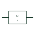
A timing relay separates the initiating signal from the later change of an output contact. The contact state, delayed transition and reset condition are independent: a timer may have immediate contacts alongside delayed contacts under the same device tag. This entry identifies the 3 clamp delay relay - energized form in the publisher's IEC-context family.
A control sequence may start an auxiliary before enabling the main load, or keep a fan running after a stop request. Trace supply, trigger and output separately, then draw a timing chart that includes what happens when the trigger ends before a delay has elapsed. The three-terminal form separates timing supply and control as defined by its actual equipment diagram. Preserve which energising or de-energising event initiates timing.
The symbol does not supply the time setting, retriggering rule or power-loss behaviour. A three-terminal timing form also needs its actual manufacturer terminal mapping; the vendor name alone does not define a universal pinout.
This entry adds the 3 clamp delay relay - energized detail to the broader timing-relay form family. The symbol does not supply the time setting, retriggering rule or power-loss behaviour. A three-terminal timing form also needs its actual manufacturer terminal mapping; the vendor name alone does not define a universal pinout.
These public references support the explanation and provide further detail. Their graphics and downloadable files remain with their publishers.
Public Time Delay Relays table explicitly lists HTD1K25 / VTD1K25 with this operating or connection form. Vendor graphics are linked, not copied.
This illustration was authored independently by Elora Grid to explain the concept. It is not reproduced from a customer drawing, an official standard graphic or a manufacturer CAD file. Its correspondence to an exact IEC or IEEE symbol identifier has not been certified.
SVG and DXF downloads contain this original artwork. DXF uses unscaled drawing units; a GA envelope supplies no product dimensions, clearances or fabrication information. Original artwork is available under CC BY 4.0. Third-party references retain their own terms.
An on-delay timer postpones a specified output transition after its timing condition becomes active.
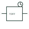
An off-delay timer holds a specified output condition for a documented period after its initiating condition is removed.
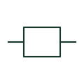
The operating element associated with a relay and its separately drawn contacts.
Elora Grid helps electrical teams work with drawings, specifications and equipment information. Explore the drafting workflow or join the early-access waitlist.