SI
Intermediate light switch plan mark
Plan mark for an intermediate switch inserted between two two-way switches to add a third control point.
IEC
Plan mark for a two-way switch used in pairs so one lighting group can be switched from two places.
In plain English
Two-way switches are installed in pairs at either end of a corridor or staircase so either switch changes the state of the lights. The IEC-style plan form draws the switch circle with strokes in two opposite directions, each with a tick, showing the changeover action.
On a plan the pair is linked by a switching line to the luminaire group. The electrician reads the pair to run strappers between the two switches; where an intermediate switch is shown between them, a third location can also control the lights.
The symbol does not show the wiring method, which can be conventional strappers or a converted arrangement. It also does not tell you the gang count unless written.
Plan mark for a two-way switch used in pairs so one lighting group can be switched from two places. In US terminology this is a three-way switch; the US four-way switch corresponds to the IEC intermediate switch.
Read the source: IEC graphical symbols for diagrams · Elementary switching devices
IEC 60617 installation-plan style (architectural and topographical installation symbols); independently drawn, not certified IEC geometry or a database identifier.
Shown as an independently authored educational illustration. Use the cited publication and drawing legend to verify the required drafting form.

Two-way switches are installed in pairs at either end of a corridor or staircase so either switch changes the state of the lights. The IEC-style plan form draws the switch circle with strokes in two opposite directions, each with a tick, showing the changeover action.
On a plan the pair is linked by a switching line to the luminaire group. The electrician reads the pair to run strappers between the two switches; where an intermediate switch is shown between them, a third location can also control the lights.
The symbol does not show the wiring method, which can be conventional strappers or a converted arrangement. It also does not tell you the gang count unless written.
In US terminology this is a three-way switch; the US four-way switch corresponds to the IEC intermediate switch.
These public references support the explanation and provide further detail. Their graphics and downloadable files remain with their publishers.
IEC graphical symbol context; independently drawn here.
Context for functional control switching.
This illustration was authored independently by Elora Grid to explain the concept. It is not reproduced from a customer drawing, an official standard graphic or a manufacturer CAD file. Its correspondence to an exact IEC or IEEE symbol identifier has not been certified.
SVG and DXF downloads contain this original artwork. DXF uses unscaled drawing units; a GA envelope supplies no product dimensions, clearances or fabrication information. Original artwork is available under CC BY 4.0. Third-party references retain their own terms.
Plan mark for an intermediate switch inserted between two two-way switches to add a third control point.

Installation plan mark for a single-pole one-way switch that turns a lighting circuit on and off from one place.
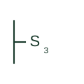
US plan symbol S3 for a three-way switch, used in pairs to control lights from two locations.
Elora Grid helps electrical teams work with drawings, specifications and equipment information. Explore the drafting workflow or join the early-access waitlist.