DI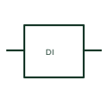
PLC digital input
A PLC digital input reads a documented discrete electrical state from field wiring.
Schematic
Two-wire PLC point form: OUT, 1st Point, 2 Wires.
In plain English
A two-wire PLC point form shows two terminal connections associated with a controller input or output point. The symbol is an interface reference, and the module data must establish whether the connection is digital, analogue, isolated or part of a shared common group. This entry identifies the out, 1st point, 2 wires form in the publisher's IEC-context family.
When tracing a field device to a PLC terminal strip, identify the rack, module, channel and both terminal numbers. Follow the common or return conductor as carefully as the signal conductor so a technician can reconcile the schematic with the module wiring sheet. The two-connection interface must be read with the load and supply arrangement. Leakage current and minimum load can matter where a powered device is connected in series with an input.
Two drawn wires do not prove that the field device is loop-powered or that a point can supply current. Electrical type, polarity, common grouping and internal protection depend on the selected module and cannot be inferred from the outline.
Two-wire PLC point form: OUT, 1st Point, 2 Wires. This entry adds the out, 1st point, 2 wires detail to the broader two-wire PLC point family. Two drawn wires do not prove that the field device is loop-powered or that a point can supply current. Electrical type, polarity, common grouping and internal protection depend on the selected module and cannot be inferred from the outline.
Read the source: PLC input and output point symbols
Autodesk IEC-60617 Symbol Preview: PLC I/O, PLCIOO2T / PLCIOO2TV. This identifies the publisher's library context; exact IEC graphics and database identities are not asserted.
Shown as an independently authored educational illustration. Use the cited publication and drawing legend to verify the required drafting form.
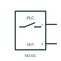
A two-wire PLC point form shows two terminal connections associated with a controller input or output point. The symbol is an interface reference, and the module data must establish whether the connection is digital, analogue, isolated or part of a shared common group. This entry identifies the out, 1st point, 2 wires form in the publisher's IEC-context family.
When tracing a field device to a PLC terminal strip, identify the rack, module, channel and both terminal numbers. Follow the common or return conductor as carefully as the signal conductor so a technician can reconcile the schematic with the module wiring sheet. The two-connection interface must be read with the load and supply arrangement. Leakage current and minimum load can matter where a powered device is connected in series with an input.
Two drawn wires do not prove that the field device is loop-powered or that a point can supply current. Electrical type, polarity, common grouping and internal protection depend on the selected module and cannot be inferred from the outline.
This entry adds the out, 1st point, 2 wires detail to the broader two-wire PLC point family. Two drawn wires do not prove that the field device is loop-powered or that a point can supply current. Electrical type, polarity, common grouping and internal protection depend on the selected module and cannot be inferred from the outline.
These public references support the explanation and provide further detail. Their graphics and downloadable files remain with their publishers.
Public PLC I/O table explicitly lists PLCIOO2T / PLCIOO2TV with this operating or connection form. Vendor graphics are linked, not copied.
This illustration was authored independently by Elora Grid to explain the concept. It is not reproduced from a customer drawing, an official standard graphic or a manufacturer CAD file. Its correspondence to an exact IEC or IEEE symbol identifier has not been certified.
SVG and DXF downloads contain this original artwork. DXF uses unscaled drawing units; a GA envelope supplies no product dimensions, clearances or fabrication information. Original artwork is available under CC BY 4.0. Third-party references retain their own terms.
A PLC digital input reads a documented discrete electrical state from field wiring.
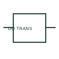
A PLC transistor output switches a documented electronic path for a field load.
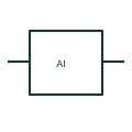
A PLC analog input measures a documented voltage, current or sensor quantity.
Elora Grid helps electrical teams work with drawings, specifications and equipment information. Explore the drafting workflow or join the early-access waitlist.