V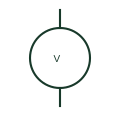
Voltmeter
A voltmeter indicates electrical potential difference between its measurement inputs.
SLD / Schematic
General circle form for any indicating instrument, with a placeholder replaced by the unit or quantity measured.
In plain English
In IEC-style diagrams an indicating instrument is drawn as a circle, and the asterisk inside is replaced by the unit symbol or quantity, such as V, A, Hz or cos φ. The general form is useful in legends and in early design drawings when the exact instrument is not yet chosen.
Because the placeholder carries all of the meaning, an unfilled general symbol tells the reader only that some reading is shown at that point. The drawing must still state the measuring connection, scaling from instrument transformers and whether the instrument is analogue or part of a digital meter.
Replace the placeholder with the actual unit before issue. Read the circle together with its measuring connections. The circle is the indicating form; recording instruments use a square and integrating instruments use a rectangle with a band.
General circle form for any indicating instrument, with a placeholder replaced by the unit or quantity measured. The circle is the indicating form; recording instruments use a square and integrating instruments use a rectangle with a band.
Read the source: IEC graphical symbols for diagrams · AutoCAD Electrical: Instrumentation and sensors

In IEC-style diagrams an indicating instrument is drawn as a circle, and the asterisk inside is replaced by the unit symbol or quantity, such as V, A, Hz or cos φ. The general form is useful in legends and in early design drawings when the exact instrument is not yet chosen.
Because the placeholder carries all of the meaning, an unfilled general symbol tells the reader only that some reading is shown at that point. The drawing must still state the measuring connection, scaling from instrument transformers and whether the instrument is analogue or part of a digital meter.
The circle is the indicating form; recording instruments use a square and integrating instruments use a rectangle with a band.
These public references support the explanation and provide further detail. Their graphics and downloadable files remain with their publishers.
IEC context for graphical symbols used in diagrams; no IEC graphic is reproduced.
Public AutoCAD Electrical listing of instrument symbols built on the indicating form.
This illustration was authored independently by Elora Grid to explain the concept. It is not reproduced from a customer drawing, an official standard graphic or a manufacturer CAD file. Its correspondence to an exact IEC or IEEE symbol identifier has not been certified.
SVG and DXF downloads contain this original artwork. DXF uses unscaled drawing units; a GA envelope supplies no product dimensions, clearances or fabrication information. Original artwork is available under CC BY 4.0. Third-party references retain their own terms.
A voltmeter indicates electrical potential difference between its measurement inputs.
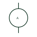
An ammeter indicates current from a direct or instrument-transformed measurement circuit.
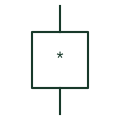
General square form for an instrument that keeps a time record of a quantity rather than just displaying it.
Elora Grid helps electrical teams work with drawings, specifications and equipment information. Explore the drafting workflow or join the early-access waitlist.