ΣCT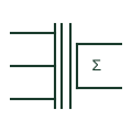
Summation current transformer
Auxiliary CT with several primary windings that adds the secondary currents of other CTs into one output.
Schematic / SLD
Auxiliary CT inserted in a CT secondary circuit to correct ratio, phase shift or provide isolation for a relay.
In plain English
An interposing CT sits between a main CT and a relay or meter. It corrects ratio mismatch, provides phase-shift compensation for transformer differential schemes, or isolates circuits, and it was standard in electromechanical differential protection before relays could compensate internally.
The interposing CT adds burden to the main CT and can introduce its own errors at high fault current. The symbol shows its presence, but its ratio, connection (star or delta) and taps must be shown beside it because they decide whether the differential scheme balances.
Read the ratio and connection group of the interposing CT. Check the added burden on the main CT. An interposing CT is an auxiliary in the secondary circuit; a main CT carries the primary circuit current.
Auxiliary CT inserted in a CT secondary circuit to correct ratio, phase shift or provide isolation for a relay. An interposing CT is an auxiliary in the secondary circuit; a main CT carries the primary circuit current.
Read the source: Current transformer symbol variants · Transformer vector-group interpretation in protection application
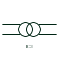
An interposing CT sits between a main CT and a relay or meter. It corrects ratio mismatch, provides phase-shift compensation for transformer differential schemes, or isolates circuits, and it was standard in electromechanical differential protection before relays could compensate internally.
The interposing CT adds burden to the main CT and can introduce its own errors at high fault current. The symbol shows its presence, but its ratio, connection (star or delta) and taps must be shown beside it because they decide whether the differential scheme balances.
An interposing CT is an auxiliary in the secondary circuit; a main CT carries the primary circuit current.
These public references support the explanation and provide further detail. Their graphics and downloadable files remain with their publishers.
Public AutoCAD Electrical current transformer family used for context; this variant is independently drawn.
Public explanation of vector-group compensation in transformer protection.
This illustration was authored independently by Elora Grid to explain the concept. It is not reproduced from a customer drawing, an official standard graphic or a manufacturer CAD file. Its correspondence to an exact IEC or IEEE symbol identifier has not been certified.
SVG and DXF downloads contain this original artwork. DXF uses unscaled drawing units; a GA envelope supplies no product dimensions, clearances or fabrication information. Original artwork is available under CC BY 4.0. Third-party references retain their own terms.
Auxiliary CT with several primary windings that adds the secondary currents of other CTs into one output.
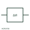
Differential relay form whose operating threshold rises in proportion to the through current, set as a relative value.
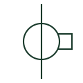
A current-measurement transformer used with metering and protection equipment.
Elora Grid helps electrical teams work with drawings, specifications and equipment information. Explore the drafting workflow or join the early-access waitlist.