t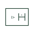
Definite-time delay qualifier for measuring relays
Qualifier added to a measuring relay symbol to show that operation follows a fixed time delay after pick-up.
Schematic / SLD
Qualifier showing that a measuring relay's operating time falls as the measured quantity rises above its setting.
In plain English
The inverse-time additional drawing mark marks a measuring element whose operating time depends on how far the measured quantity exceeds the setting: the larger the overcurrent, the faster the trip. On drawings it appears with overcurrent and earth-fault elements that are graded against fuses and downstream relays.
The additional drawing mark does not name the curve. Standard inverse, very inverse and extremely inverse curves grade very differently, and the curve type, time multiplier and pick-up current must be taken from the protection settings.
Identify the curve type from the settings record. Read with the grading study for the feeder. An inverse-time additional drawing mark marks a current-dependent delay; a definite-time additional drawing mark marks a fixed delay.
additional drawing mark showing that a measuring relay's operating time falls as the measured quantity rises above its setting. An inverse-time additional drawing mark marks a current-dependent delay; a definite-time additional drawing mark marks a fixed delay.
Read the source: IEC graphical symbols for diagrams · Fundamental characteristics of a circuit-breaker
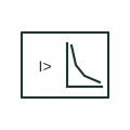
The inverse-time qualifier marks a measuring element whose operating time depends on how far the measured quantity exceeds the setting: the larger the overcurrent, the faster the trip. On drawings it appears with overcurrent and earth-fault elements that are graded against fuses and downstream relays.
The qualifier does not name the curve. Standard inverse, very inverse and extremely inverse curves grade very differently, and the curve type, time multiplier and pick-up current must be taken from the protection settings.
An inverse-time qualifier marks a current-dependent delay; a definite-time qualifier marks a fixed delay.
These public references support the explanation and provide further detail. Their graphics and downloadable files remain with their publishers.
IEC context for graphical symbols used in diagrams; no IEC graphic is reproduced.
Public explanation of time-current characteristics used in protective devices.
This illustration was authored independently by Elora Grid to explain the concept. It is not reproduced from a customer drawing, an official standard graphic or a manufacturer CAD file. Its correspondence to an exact IEC or IEEE symbol identifier has not been certified.
SVG and DXF downloads contain this original artwork. DXF uses unscaled drawing units; a GA envelope supplies no product dimensions, clearances or fabrication information. Original artwork is available under CC BY 4.0. Third-party references retain their own terms.
Qualifier added to a measuring relay symbol to show that operation follows a fixed time delay after pick-up.

An overcurrent function with a documented time characteristic.
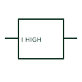
A maximum-current relay changes its output when the measured current meets a configured high-current condition.
Elora Grid helps electrical teams work with drawings, specifications and equipment information. Explore the drafting workflow or join the early-access waitlist.