CT 2SEC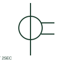
Current transformer with two secondaries
A CT with two secondary windings supplies two documented secondary circuits.
SLD / Schematic
CT with several independent magnetic cores on one primary, each with its own secondary for metering or protection.
In plain English
A multi-core CT has one primary passing through two or more separate cores, each with its own secondary winding. Typical MV and higher-voltage CTs have one metering core and one or more protection cores, so the single-line diagram shows each core as its own ring on the primary with its ratio and class beside it.
Separate cores mean a fault-saturated protection core does not disturb the metering core, and each can have a different accuracy class. The symbol shows how many cores exist but not which relay or meter each feeds, so every core needs its own designation and cross-reference.
Count the cores and read each ratio and class separately. Follow each secondary to its own relay or meter. A multi-core CT has separate magnetic cores; a CT with two secondaries on a common core shares one magnetic circuit.
CT with several independent magnetic cores on one primary, each with its own secondary for metering or protection. A multi-core CT has separate magnetic cores; a CT with two secondaries on a common core shares one magnetic circuit.
Read the source: Indoor current and voltage transformers · Current transformer symbol variants
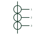
A multi-core CT has one primary passing through two or more separate cores, each with its own secondary winding. Typical MV and HV CTs have one metering core and one or more protection cores, so the single-line diagram shows each core as its own ring on the primary with its ratio and class beside it.
Separate cores mean a fault-saturated protection core does not disturb the metering core, and each can have a different accuracy class. The symbol shows how many cores exist but not which relay or meter each feeds, so every core needs its own designation and cross-reference.
A multi-core CT has separate magnetic cores; a CT with two secondaries on a common core shares one magnetic circuit.
These public references support the explanation and provide further detail. Their graphics and downloadable files remain with their publishers.
Public manufacturer overview of indoor current and voltage instrument transformers.
Public AutoCAD Electrical current transformer family used for context; this variant is independently drawn.
This illustration was authored independently by Elora Grid to explain the concept. It is not reproduced from a customer drawing, an official standard graphic or a manufacturer CAD file. Its correspondence to an exact IEC or IEEE symbol identifier has not been certified.
SVG and DXF downloads contain this original artwork. DXF uses unscaled drawing units; a GA envelope supplies no product dimensions, clearances or fabrication information. Original artwork is available under CC BY 4.0. Third-party references retain their own terms.
A CT with two secondary windings supplies two documented secondary circuits.
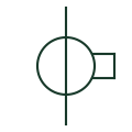
A current-measurement transformer used with metering and protection equipment.
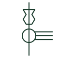
Toroidal CT mounted around a transformer or breaker bushing, often with a tapped multi-ratio secondary.
Elora Grid helps electrical teams work with drawings, specifications and equipment information. Explore the drafting workflow or join the early-access waitlist.