CT RES
Residual connection of phase CTs
A residual CT connection combines secondary currents from phase CTs to obtain a residual-current input.
SLD / Schematic
Measuring relay fed from a CT in a neutral conductor or star-point connection, responding to neutral current.
In plain English
This relay form is used where a CT is installed in a neutral conductor or in the earthing connection of a transformer or generator star point. Current there indicates earth faults or, in four-wire systems, heavy unbalance and triplen harmonic loading, depending on where the CT sits.
The symbol identifies the measured conductor but not the purpose. A neutral CT in the star-point earth lead gives standby earth-fault protection, while one in the four-wire neutral of a feeder sees load unbalance as well, so settings and grading differ greatly.
Confirm whether the CT is in the neutral conductor or the earthing lead. Check grading against downstream earth-fault devices. A neutral-current relay measures one neutral path; a residual connection sums the three phase CTs to derive the same quantity.
Measuring relay fed from a CT in a neutral conductor or star-point connection, responding to neutral current. A neutral-current relay measures one neutral path; a residual connection sums the three phase CTs to derive the same quantity.
Read the source: AutoCAD Electrical: Current monitoring relays · IEC graphical symbols for diagrams
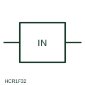
This relay form is used where a CT is installed in a neutral conductor or in the earthing connection of a transformer or generator star point. Current there indicates earth faults or, in four-wire systems, heavy unbalance and triplen harmonic loading, depending on where the CT sits.
The symbol identifies the measured conductor but not the purpose. A neutral CT in the star-point earth lead gives standby earth-fault protection, while one in the four-wire neutral of a feeder sees load unbalance as well, so settings and grading differ greatly.
A neutral-current relay measures one neutral path; a residual connection sums the three phase CTs to derive the same quantity.
These public references support the explanation and provide further detail. Their graphics and downloadable files remain with their publishers.
Public AutoCAD Electrical relay listing that names the In Neutral block; the illustration is independently drawn.
IEC context for graphical symbols used in diagrams; no IEC graphic is reproduced.
This illustration was authored independently by Elora Grid to explain the concept. It is not reproduced from a customer drawing, an official standard graphic or a manufacturer CAD file. Its correspondence to an exact IEC or IEEE symbol identifier has not been certified.
SVG and DXF downloads contain this original artwork. DXF uses unscaled drawing units; a GA envelope supplies no product dimensions, clearances or fabrication information. Original artwork is available under CC BY 4.0. Third-party references retain their own terms.
A residual CT connection combines secondary currents from phase CTs to obtain a residual-current input.
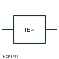
Measuring relay form that operates on current flowing to earth, fed from a residual connection or core-balance CT.

An overcurrent function with a documented time characteristic.
Elora Grid helps electrical teams work with drawings, specifications and equipment information. Explore the drafting workflow or join the early-access waitlist.