COMP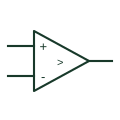
Voltage comparator
Compares two analogue input voltages and produces the documented output-state indication.
Schematic
Comparator or op-amp with positive feedback to the plus input, creating two switching thresholds.
In plain English
Adding a resistor from the output to the non-inverting input of a comparator gives positive feedback, so the switching threshold depends on the current output state. The result is hysteresis: the circuit switches at one level on a rising input and a lower level on a falling input, rejecting noise near the threshold.
This circuit is used for level detection from slow analogue signals such as temperature, battery voltage or tank level. The drawing should state both thresholds, or the resistor values and reference from which they are derived.
The circuit symbol does not show the thresholds directly and they depend on output swing, so a part with rail-to-rail or open-collector output changes the calculation.
Comparator or op-amp with positive feedback to the plus input, creating two switching thresholds. An op-amp amplifier uses negative feedback to the minus input; this circuit uses positive feedback.
Read the source: TLV3201 — voltage comparison · University tutorials: amplifier configurations and signal processing
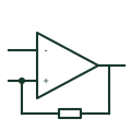
Adding a resistor from the output to the non-inverting input of a comparator gives positive feedback, so the switching threshold depends on the current output state. The result is hysteresis: the circuit switches at one level on a rising input and a lower level on a falling input, rejecting noise near the threshold.
This circuit is used for level detection from slow analogue signals such as temperature, battery voltage or tank level. The drawing should state both thresholds, or the resistor values and reference from which they are derived.
The circuit symbol does not show the thresholds directly and they depend on output swing, so a part with rail-to-rail or open-collector output changes the calculation.
An op-amp amplifier uses negative feedback to the minus input; this circuit uses positive feedback.
These public references support the explanation and provide further detail. Their graphics and downloadable files remain with their publishers.
Manufacturer comparator documentation.
Public tutorial material on comparator and feedback configurations.
This illustration was authored independently by Elora Grid to explain the concept. It is not reproduced from a customer drawing, an official standard graphic or a manufacturer CAD file. Its correspondence to an exact IEC or IEEE symbol identifier has not been certified.
SVG and DXF downloads contain this original artwork. DXF uses unscaled drawing units; a GA envelope supplies no product dimensions, clearances or fabrication information. Original artwork is available under CC BY 4.0. Third-party references retain their own terms.
Compares two analogue input voltages and produces the documented output-state indication.
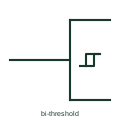
Small hysteresis loop mark showing a Schmitt-trigger function or a bi-threshold input.

A non-inverting digital element with separate rising and falling input thresholds.
Elora Grid helps electrical teams work with drawings, specifications and equipment information. Explore the drafting workflow or join the early-access waitlist.