RC
Rogowski coil current sensor
Air-cored coil around a conductor whose output voltage is proportional to the rate of change of current.
SLD / Schematic
Current sensor using light in an optical fibre around the conductor, whose polarisation changes with the magnetic field.
In plain English
An optical current sensor measures current from the rotation of polarised light in a fibre wound around the conductor, a magneto-optic effect proportional to the enclosed magnetic field. It is used in higher-voltage and DC applications where conventional CTs are bulky or where saturation and insulation are concerns.
The sensor head connects through fibre to an electronics unit, which usually outputs digital sampled values to protection and metering devices. The symbol does not show the electronics unit, its supply or the data interface, all of which must be drawn for the measurement chain to be complete.
Find the electronics unit that converts the optical signal. Check the data interface to protection devices. An optical current sensor uses light in fibre; a conventional CT uses magnetic induction in a winding.
Current sensor using light in an optical fibre around the conductor, whose polarisation changes with the magnetic field. An optical current sensor uses light in fibre; a conventional CT uses magnetic induction in a winding.
Read the source: Indoor current and voltage transformers · IEC graphical symbols for diagrams
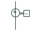
An optical current sensor measures current from the rotation of polarised light in a fibre wound around the conductor, a magneto-optic effect proportional to the enclosed magnetic field. It is used in HV and DC applications where conventional CTs are bulky or where saturation and insulation are concerns.
The sensor head connects through fibre to an electronics unit, which usually outputs digital sampled values to protection and metering devices. The symbol does not show the electronics unit, its supply or the data interface, all of which must be drawn for the measurement chain to be complete.
An optical current sensor uses light in fibre; a conventional CT uses magnetic induction in a winding.
These public references support the explanation and provide further detail. Their graphics and downloadable files remain with their publishers.
Public manufacturer overview of indoor current and voltage instrument transformers.
IEC context for graphical symbols used in diagrams; no IEC graphic is reproduced.
This illustration was authored independently by Elora Grid to explain the concept. It is not reproduced from a customer drawing, an official standard graphic or a manufacturer CAD file. Its correspondence to an exact IEC or IEEE symbol identifier has not been certified.
SVG and DXF downloads contain this original artwork. DXF uses unscaled drawing units; a GA envelope supplies no product dimensions, clearances or fabrication information. Original artwork is available under CC BY 4.0. Third-party references retain their own terms.
Air-cored coil around a conductor whose output voltage is proportional to the rate of change of current.
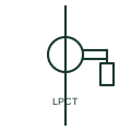
Small iron-core CT with an integral shunt that delivers a low-level voltage signal instead of a standard secondary current.

A current-measurement transformer used with metering and protection equipment.
Elora Grid helps electrical teams work with drawings, specifications and equipment information. Explore the drafting workflow or join the early-access waitlist.