PH LOSS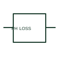
Phase-loss monitoring relay
A phase-loss relay supervises the presence of the specified phases in a three-phase system.
SLD / Schematic
Instrument that shows whether three-phase supply rotation is positive or reversed before motors are run or sources paralleled.
In plain English
A phase-sequence indicator connects to all three phases and shows whether rotation is L1-L2-L3 or reversed. It is used when commissioning motors, generators and supply changes, because wrong rotation reverses motors and prevents correct paralleling.
The instrument gives a check at one moment and does not protect anything on its own. If permanent protection against reversed rotation is needed, a phase-sequence monitoring relay with contacts must be shown instead of, or as well as, the indicator.
Confirm all three phases are connected in the stated order. Check whether a protective relay is also required. A phase-sequence indicator only displays rotation; a phase monitoring relay acts on incorrect rotation or loss of phase.
Instrument that shows whether three-phase supply rotation is positive or reversed before motors are run or sources paralleled. A phase-sequence indicator only displays rotation; a phase monitoring relay acts on incorrect rotation or loss of phase.
Read the source: IEC graphical symbols for diagrams

A phase-sequence indicator connects to all three phases and shows whether rotation is L1-L2-L3 or reversed. It is used when commissioning motors, generators and supply changes, because wrong rotation reverses motors and prevents correct paralleling.
The instrument gives a check at one moment and does not protect anything on its own. If permanent protection against reversed rotation is needed, a phase-sequence monitoring relay with contacts must be shown instead of, or as well as, the indicator.
A phase-sequence indicator only displays rotation; a phase monitoring relay acts on incorrect rotation or loss of phase.
These public references support the explanation and provide further detail. Their graphics and downloadable files remain with their publishers.
IEC context for graphical symbols used in diagrams; no IEC graphic is reproduced.
This illustration was authored independently by Elora Grid to explain the concept. It is not reproduced from a customer drawing, an official standard graphic or a manufacturer CAD file. Its correspondence to an exact IEC or IEEE symbol identifier has not been certified.
SVG and DXF downloads contain this original artwork. DXF uses unscaled drawing units; a GA envelope supplies no product dimensions, clearances or fabrication information. Original artwork is available under CC BY 4.0. Third-party references retain their own terms.
A phase-loss relay supervises the presence of the specified phases in a three-phase system.
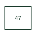
Supervises phase order or voltage imbalance using the selected device's voltage inputs.
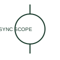
A synchronoscope indicates the phase relationship and relative frequency behaviour of two AC sources.
Elora Grid helps electrical teams work with drawings, specifications and equipment information. Explore the drafting workflow or join the early-access waitlist.