PHASE
Phase-angle meter
A phase-angle meter indicates the phase relationship between documented signals.
SLD / Schematic
Device that measures voltage and current phasors with precise time stamps so angles can be compared across a network.
In plain English
A phasor measurement unit samples voltages and currents and calculates magnitude and phase angle referenced to an absolute time source, normally GPS. Data from many PMUs can then be compared to see angle differences across a network, oscillations and islanding.
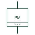
On a single-line diagram the PMU is drawn with its CT and VT inputs and a time input. The symbol does not show reporting rate, the communications path to a data concentrator or the measurement class, which together determine whether the data suits protection, control or monitoring.
Check the time synchronisation input. Trace CT and VT inputs to the measuring point. A PMU reports time-aligned phasors; a phase-angle meter shows a local angle between two inputs.
Device that measures voltage and current phasors with precise time stamps so angles can be compared across a network. A PMU reports time-aligned phasors; a phase-angle meter shows a local angle between two inputs.
Read the source: SEL 2022 Product and Solution Guide: published protection function tables · IEEE/ANSI 315-1975: graphic symbols for electrical and electronics diagrams

A phasor measurement unit samples voltages and currents and calculates magnitude and phase angle referenced to an absolute time source, normally GPS. Data from many PMUs can then be compared to see angle differences across a network, oscillations and islanding.
On a single-line diagram the PMU is drawn with its CT and VT inputs and a time input. The symbol does not show reporting rate, the communications path to a data concentrator or the measurement class, which together determine whether the data suits protection, control or monitoring.
A PMU reports time-aligned phasors; a phase-angle meter shows a local angle between two inputs.
These public references support the explanation and provide further detail. Their graphics and downloadable files remain with their publishers.
Public product guide covering synchrophasor-capable devices.
IEEE standards context; the PMU block is a functional illustration only.
This illustration was authored independently by Elora Grid to explain the concept. It is not reproduced from a customer drawing, an official standard graphic or a manufacturer CAD file. Its correspondence to an exact IEC or IEEE symbol identifier has not been certified.
SVG and DXF downloads contain this original artwork. DXF uses unscaled drawing units; a GA envelope supplies no product dimensions, clearances or fabrication information. Original artwork is available under CC BY 4.0. Third-party references retain their own terms.
A phase-angle meter indicates the phase relationship between documented signals.
Digital panel meter that measures voltage, current, power, energy and power factor from one set of CT and VT inputs.

A transformer providing a voltage signal for metering or protection.
Elora Grid helps electrical teams work with drawings, specifications and equipment information. Explore the drafting workflow or join the early-access waitlist.