BD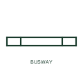
Feeder busway
A busway run used purely to carry power between two points, drawn as a distinct trunking line without tap-off points.
SLD / GA
Busway with tap-off outlets along its length, drawn with outlet marks where plug-in units can be connected.
In plain English
Plug-in busway distributes power along its route through outlets into which tap-off units can be inserted. It is common in rising mains in multi-storey buildings, factory floors and data halls, where loads change and new feeders are added without rewiring.
The symbol shows that outlets exist but not which are used. Tap-off units actually fitted are drawn separately with their protective devices. Readers should not assume every outlet mark represents a connected load, and voltage drop calculations should use the actual tap-off positions.
Distinguish outlet positions from fitted tap-off units. Check voltage drop to the most remote tap-off. Plug-in busway has outlets for tap-off units; feeder busway carries power point to point only.
Busway with tap-off outlets along its length, drawn with outlet marks where plug-in units can be connected. Plug-in busway has outlets for tap-off units; feeder busway carries power point to point only.
Read the source: Canalis busbar trunking systems · Electrical installation design methodology and references
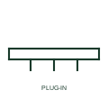
Plug-in busway distributes power along its route through outlets into which tap-off units can be inserted. It is common in rising mains in multi-storey buildings, factory floors and data halls, where loads change and new feeders are added without rewiring.
The symbol shows that outlets exist but not which are used. Tap-off units actually fitted are drawn separately with their protective devices. Readers should not assume every outlet mark represents a connected load, and voltage drop calculations should use the actual tap-off positions.
Plug-in busway has outlets for tap-off units; feeder busway carries power point to point only.
These public references support the explanation and provide further detail. Their graphics and downloadable files remain with their publishers.
Manufacturer busbar trunking ranges with tap-off outlets.
Installation design methodology including busway distribution.
This illustration was authored independently by Elora Grid to explain the concept. It is not reproduced from a customer drawing, an official standard graphic or a manufacturer CAD file. Its correspondence to an exact IEC or IEEE symbol identifier has not been certified.
SVG and DXF downloads contain this original artwork. DXF uses unscaled drawing units; a GA envelope supplies no product dimensions, clearances or fabrication information. Original artwork is available under CC BY 4.0. Third-party references retain their own terms.
A busway run used purely to carry power between two points, drawn as a distinct trunking line without tap-off points.

The connection of an outgoing circuit to a plug-in busway through a tap-off unit, usually containing a protective device.
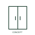
A tap-off unit connects an outgoing circuit to the selected busbar trunking system.
Elora Grid helps electrical teams work with drawings, specifications and equipment information. Explore the drafting workflow or join the early-access waitlist.