TB MULTI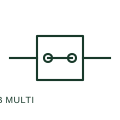
Multi-conductor terminal block
A multi-conductor terminal provides several connection points for its documented electrical path.
Schematic
A terminal assembly that splits one incoming conductor into several outgoing conductors on a common bar.
In plain English
A power distribution block takes one large incoming conductor and distributes it to several smaller outgoing conductors on a shared conducting bar, saving space compared with stacking lugs on one terminal. It is used in control panels to distribute supply to several circuit breakers or loads.
The symbol shows the shared node and terminal count but not the short-circuit current rating, which varies widely between products and must suit the available fault current. Outgoing conductors connected to a distribution block usually need upstream protection sized for the smallest outgoing conductor unless tap rules allow otherwise.
Check the block's short-circuit current rating against the panel rating. Confirm outgoing conductor protection. A power distribution block is one node with many terminals; a multi-conductor terminal block is a single terminal accepting several wires.
A terminal assembly that splits one incoming conductor into several outgoing conductors on a common bar. A power distribution block is one node with many terminals; a multi-conductor terminal block is a single terminal accepting several wires.
Read the source: IEC-60617 Symbol Preview: Power Distribution Blocks · Terminal block functional families
Autodesk IEC-60617 Symbol Preview: Power Distribution Blocks; vendor family reference, not certified IEC geometry.
Shown as an independently authored educational illustration. Use the cited publication and drawing legend to verify the required drafting form.

A power distribution block takes one large incoming conductor and distributes it to several smaller outgoing conductors on a shared conducting bar, saving space compared with stacking lugs on one terminal. It is used in control panels to distribute supply to several circuit breakers or loads.
The symbol shows the shared node and terminal count but not the short-circuit current rating, which varies widely between products and must suit the available fault current. Outgoing conductors connected to a distribution block usually need upstream protection sized for the smallest outgoing conductor unless tap rules allow otherwise.
A power distribution block is one node with many terminals; a multi-conductor terminal block is a single terminal accepting several wires.
These public references support the explanation and provide further detail. Their graphics and downloadable files remain with their publishers.
Public IEC-oriented preview page listing power distribution block forms.
Manufacturer terminal block functional families.
This illustration was authored independently by Elora Grid to explain the concept. It is not reproduced from a customer drawing, an official standard graphic or a manufacturer CAD file. Its correspondence to an exact IEC or IEEE symbol identifier has not been certified.
SVG and DXF downloads contain this original artwork. DXF uses unscaled drawing units; a GA envelope supplies no product dimensions, clearances or fabrication information. Original artwork is available under CC BY 4.0. Third-party references retain their own terms.
A multi-conductor terminal provides several connection points for its documented electrical path.
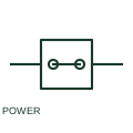
A high-current terminal provides a documented connection for large conductors and power circuits.
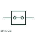
A terminal bridge intentionally connects specified terminal points to a common potential.
Elora Grid helps electrical teams work with drawings, specifications and equipment information. Explore the drafting workflow or join the early-access waitlist.