I HIGH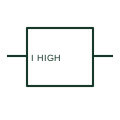
Maximum-current monitoring relay
A maximum-current relay changes its output when the measured current meets a configured high-current condition.
SLD / Schematic
Measuring relay that operates when current flows in the opposite direction to normal, such as back-feed into a DC source.
In plain English
A reverse-current relay compares the direction of current with a reference and operates when current flows the wrong way. Classic uses are DC generators and battery chargers in parallel, where a failed source would otherwise draw current from the bus, and rectifier feeders where back-feed indicates a fault.
On the schematic the relay box carries a current quantity with a direction additional drawing mark, and its contacts are drawn elsewhere in the trip or alarm circuit. The box does not show the pick-up level or time delay, and in AC systems the equivalent requirement is usually met with a directional power function rather than a simple current-direction element.
Identify which direction is treated as normal for the source. Find the contacts that trip or disconnect the source. A reverse-current relay responds to current direction; a maximum-current relay responds to magnitude regardless of direction.
Measuring relay that operates when current flows in the opposite direction to normal, such as back-feed into a DC source. A reverse-current relay responds to current direction; a maximum-current relay responds to magnitude regardless of direction.
Read the source: AutoCAD Electrical: Current monitoring relays · IEC graphical symbols for diagrams
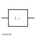
A reverse-current relay compares the direction of current with a reference and operates when current flows the wrong way. Classic uses are DC generators and battery chargers in parallel, where a failed source would otherwise draw current from the bus, and rectifier feeders where back-feed indicates a fault.
On the schematic the relay box carries a current quantity with a direction qualifier, and its contacts are drawn elsewhere in the trip or alarm circuit. The box does not show the pick-up level or time delay, and in AC systems the equivalent requirement is usually met with a directional power function rather than a simple current-direction element.
A reverse-current relay responds to current direction; a maximum-current relay responds to magnitude regardless of direction.
These public references support the explanation and provide further detail. Their graphics and downloadable files remain with their publishers.
Public AutoCAD Electrical relay listing that names the Come Back Current Protection block; the illustration is independently drawn.
IEC context for graphical symbols used in diagrams; no IEC graphic is reproduced.
This illustration was authored independently by Elora Grid to explain the concept. It is not reproduced from a customer drawing, an official standard graphic or a manufacturer CAD file. Its correspondence to an exact IEC or IEEE symbol identifier has not been certified.
SVG and DXF downloads contain this original artwork. DXF uses unscaled drawing units; a GA envelope supplies no product dimensions, clearances or fabrication information. Original artwork is available under CC BY 4.0. Third-party references retain their own terms.
A maximum-current relay changes its output when the measured current meets a configured high-current condition.

A function responding to power with a specified direction and operating condition.
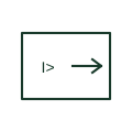
Arrow qualifier on a measuring relay showing that it operates only for power or current in the marked direction.
Elora Grid helps electrical teams work with drawings, specifications and equipment information. Explore the drafting workflow or join the early-access waitlist.