SE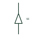
Single-core cable sealing end
The termination at the end of a single-core cable where it is sealed and connected to an overhead line or equipment.
IEC
A plug-in screened termination that connects a medium voltage cable to an equipment bushing and can be separated.
In plain English
Separable connectors, such as elbow and T-body connectors, terminate a medium voltage cable onto a bushing so that the cable can be disconnected without cutting it. They appear on ring main units, pad-mounted transformers and switchgear with standardised bushing interfaces, and the T-body form often allows a second cable or a surge arrester to be stacked behind it.
The drawing symbol identifies the plug-in interface but not the interface type, current rating or whether the connector is load-break or dead-break. Those details determine whether it may be operated under load and must be given in text. A dead-break connector must never be separated while supplied with operating power.
Check whether the connector is load-break or dead-break. Look for stacked arresters or second cables on T-bodies. A separable connector plugs onto a bushing and can be removed; a sealing end is a fixed termination.
A plug-in screened termination that connects a medium voltage cable to an equipment bushing and can be separated. A separable connector plugs onto a bushing and can be removed; a sealing end is a fixed termination.
Read the source: Elastimold underground cable accessories · IEEE/ANSI 315-1975: graphic symbols for electrical and electronics diagrams
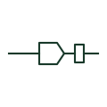
Separable connectors, such as elbow and T-body connectors, terminate a medium voltage cable onto a bushing so that the cable can be disconnected without cutting it. They appear on ring main units, pad-mounted transformers and switchgear with standardised bushing interfaces, and the T-body form often allows a second cable or a surge arrester to be stacked behind it.
The drawing symbol identifies the plug-in interface but not the interface type, current rating or whether the connector is load-break or dead-break. Those details determine whether it may be operated under load and must be given in text. A dead-break connector must never be separated while energised.
A separable connector plugs onto a bushing and can be removed; a sealing end is a fixed termination.
These public references support the explanation and provide further detail. Their graphics and downloadable files remain with their publishers.
Manufacturer context for separable cable connectors and accessories.
Standards context for connector graphics.
This illustration was authored independently by Elora Grid to explain the concept. It is not reproduced from a customer drawing, an official standard graphic or a manufacturer CAD file. Its correspondence to an exact IEC or IEEE symbol identifier has not been certified.
SVG and DXF downloads contain this original artwork. DXF uses unscaled drawing units; a GA envelope supplies no product dimensions, clearances or fabrication information. Original artwork is available under CC BY 4.0. Third-party references retain their own terms.
The termination at the end of a single-core cable where it is sealed and connected to an overhead line or equipment.
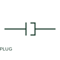
A plug-half representation identifies one side of a detachable connector.
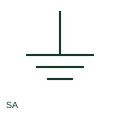
A surge arrester diverts a documented surge-related current through its protective path.
Elora Grid helps electrical teams work with drawings, specifications and equipment information. Explore the drafting workflow or join the early-access waitlist.