G 3PH SYNC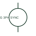
Three-phase synchronous generator
A three-phase synchronous generator supplies a documented AC source associated with its mechanical prime mover and excitation system.
SLD / Schematic
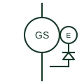
A synchronous alternator shown with its exciter machine and rotating rectifier, as used on most generating sets.
In plain English
Most modern generating sets use a brushless excitation system: a small exciter generator on the same shaft feeds a rotating diode rectifier, which supplies DC to the main field without slip rings. The automatic voltage regulator controls the exciter field, and some sets add a permanent-magnet pilot exciter to power the regulator independently of the output voltage.
Schematics draw the main generator circle, a smaller exciter circle on the same shaft line and a rectifier bridge between them, with the regulator connected to the exciter field. Single-line diagrams often reduce this to the main machine with a note, so the expanded form usually appears on the generator control schematic.
The symbol does not give the regulator type, the excitation support during short circuits, or whether a pilot exciter is fitted. Those determine whether the set can sustain fault current long enough for downstream protection to operate.
A synchronous alternator shown with its exciter machine and rotating rectifier, as used on most generating sets. This form shows the excitation chain explicitly; the plain synchronous generator symbol shows only the main machine.
Read the source: T-030 liquid-cooled generator set application manual · Generator symbol variants
Most modern generating sets use a brushless excitation system: a small exciter generator on the same shaft feeds a rotating diode rectifier, which supplies DC to the main field without slip rings. The automatic voltage regulator controls the exciter field, and some sets add a permanent-magnet pilot exciter to power the regulator independently of the output voltage.
Schematics draw the main generator circle, a smaller exciter circle on the same shaft line and a rectifier bridge between them, with the regulator connected to the exciter field. Single-line diagrams often reduce this to the main machine with a note, so the expanded form usually appears on the generator control schematic.
The symbol does not give the regulator type, the excitation support during short circuits, or whether a pilot exciter is fitted. Those determine whether the set can sustain fault current long enough for downstream protection to operate.
This form shows the excitation chain explicitly; the plain synchronous generator symbol shows only the main machine.
These public references support the explanation and provide further detail. Their graphics and downloadable files remain with their publishers.
Public generator-set application manual describing alternator excitation arrangements.
Public synchronous generator symbol variants.
This illustration was authored independently by Elora Grid to explain the concept. It is not reproduced from a customer drawing, an official standard graphic or a manufacturer CAD file. Its correspondence to an exact IEC or IEEE symbol identifier has not been certified.
SVG and DXF downloads contain this original artwork. DXF uses unscaled drawing units; a GA envelope supplies no product dimensions, clearances or fabrication information. Original artwork is available under CC BY 4.0. Third-party references retain their own terms.
A three-phase synchronous generator supplies a documented AC source associated with its mechanical prime mover and excitation system.
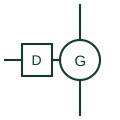
A compression-ignition engine coupled to an alternator, shown as a source on microgrid and standby power single-line diagrams.
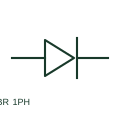
A single-phase bridge rectifier converts its specified AC input to a DC output through a bridge arrangement.
Supervises an exciter or DC generator condition in a machine control arrangement.
Elora Grid helps electrical teams work with drawings, specifications and equipment information. Explore the drafting workflow or join the early-access waitlist.