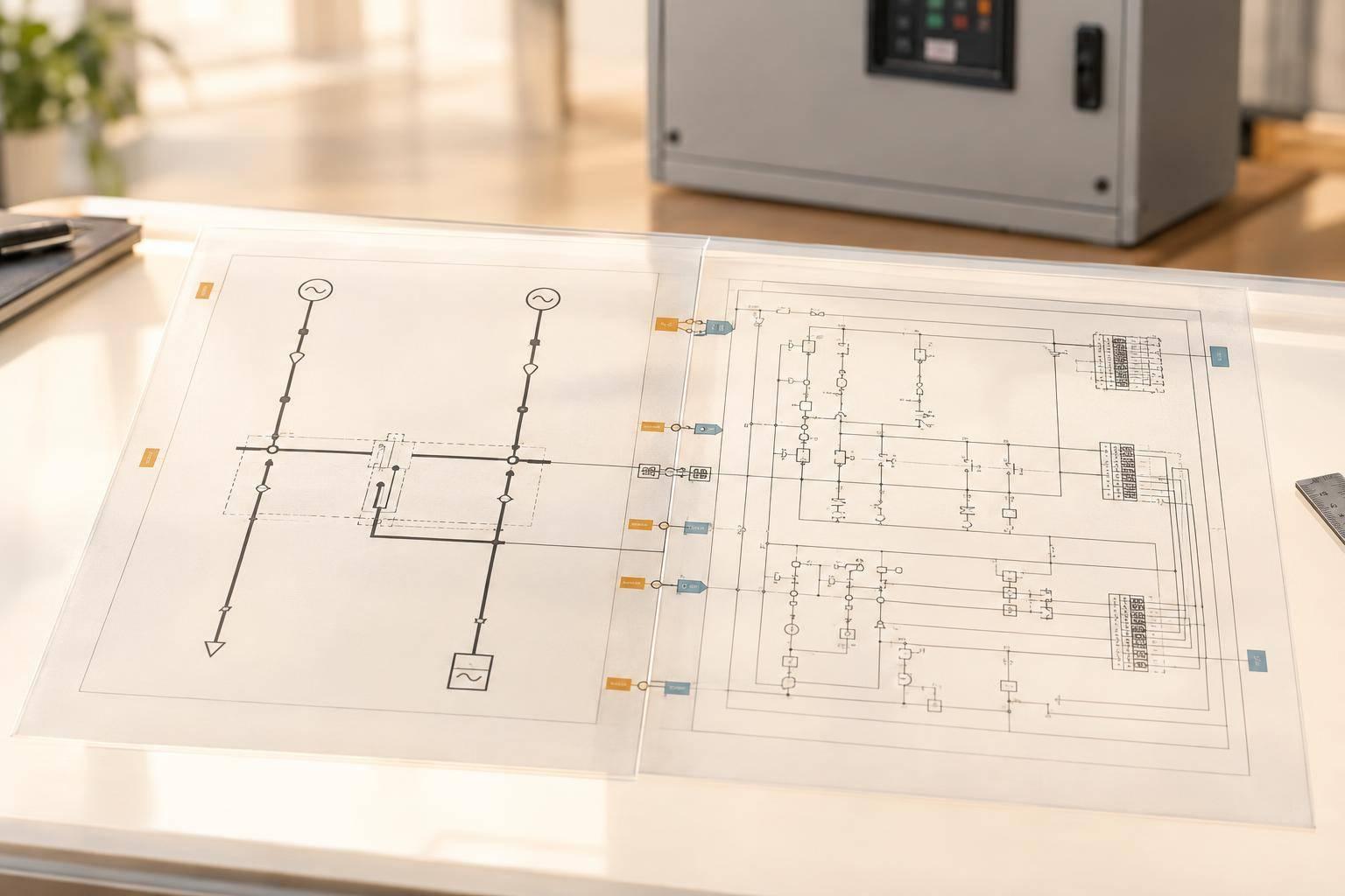
ATS External Wiring: Single Lines vs. Schematics
An ATS single-line diagram shows the power path. A control schematic shows the transfer logic. Before issue, check both against approved manufacturer wiring documents - symbols alone do not establish field terminals.
The review covers 3 linked checks: source-to-load connections and ratings; generator-start, transfer, and alarm signals; and matching tags, terminals, and revisions. One shared equipment-and-interface register keeps those details aligned.
Quick Comparison
| Check | Single-line diagram | Control schematic |
|---|---|---|
| Main purpose | Trace power from sources through the ATS to loads | Trace sensing, commands, interlocks, and status |
| Key details | Voltage, current ratings, protection, poles, and neutral arrangement | Control power, signal types, contacts, and transfer timing |
| Field connections | Shows the power arrangement | Shows signal functions; approved wiring documents establish terminations |
Resolve mismatches before release. Confirm both ends of each external connection, and check wiring separation against installation documents and equipment instructions.
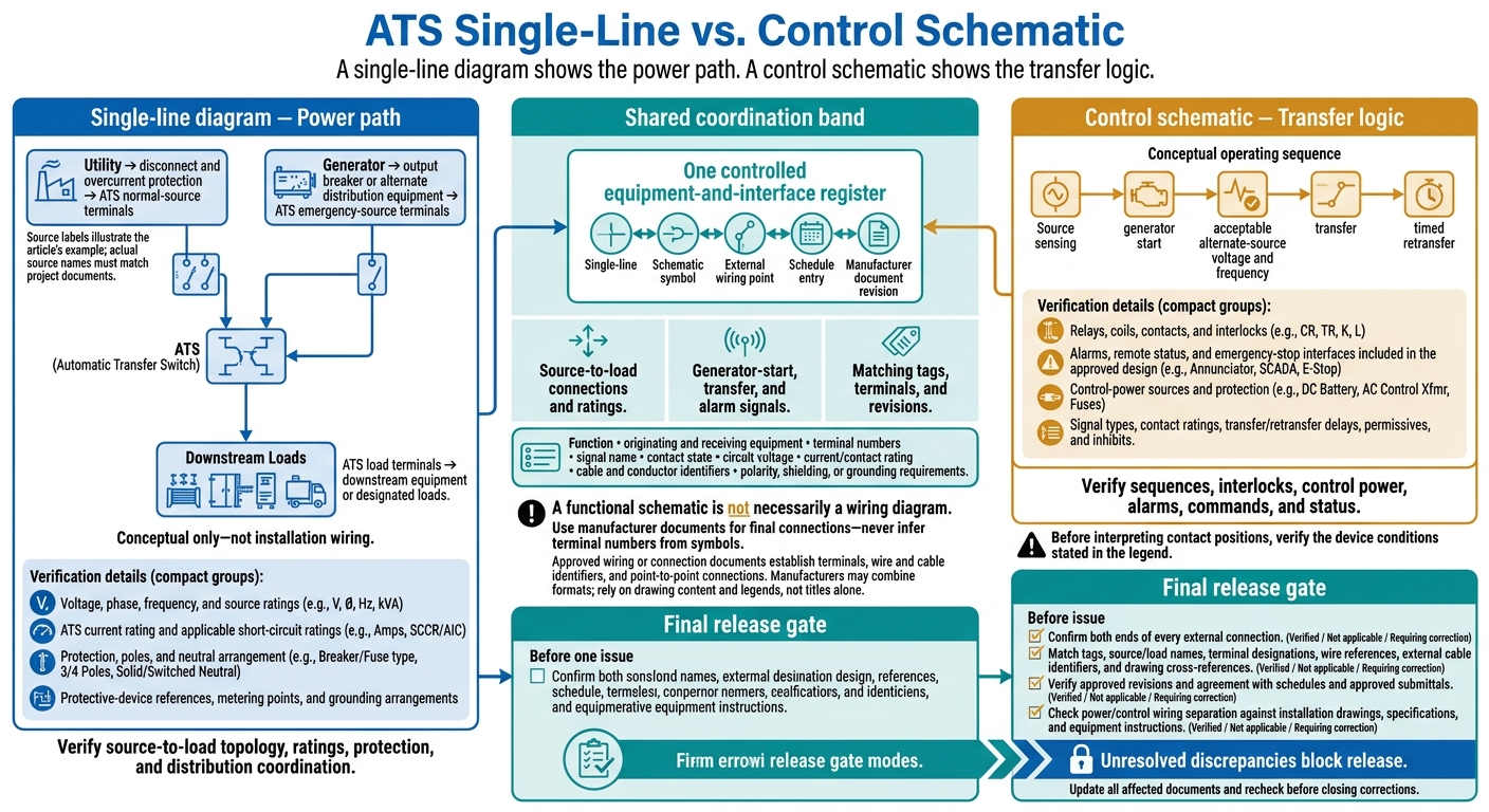
ATS Single-Line vs. Control Schematic: What to Verify
Automatic Transfer Switch Explained – Wiring, PLC Logic & Components
sbb-itb-f008923
Single-Line Diagrams vs. Control Schematics
A single-line diagram shows how power flows; a control schematic shows how the system operates. A complete power arrangement doesn’t prove that the transfer logic works. And correct control logic doesn’t confirm equipment ratings or distribution connections.
The table below shows what each drawing helps you verify. The next subsections explain how to read them.
| Category | Single-line diagram | Control schematic |
|---|---|---|
| Representation | Simplified symbolic power path; one line can represent a three-phase circuit | Functional logic showing contacts, coils, relays, sensing circuits, and signal paths |
| Purpose | Verify source-to-load topology, ratings, protection, and distribution coordination | Verify sequences, interlocks, control power, alarms, commands, and status |
| Detail | Equipment and circuit-level information | Device, function, and signal details - not physical routing |
| ATS information shown | Sources, ATS, and loads | Transfer logic and external signals |
Start with the power path, then check the control path.
Single Lines: Power Sources, ATS, and Loads
Trace utility power through its disconnect and overcurrent protection to the ATS normal-source terminals. Next, follow the generator through its output breaker or alternate distribution equipment to the ATS emergency-source terminals. Then trace the ATS load terminals to downstream equipment or designated loads.
Show voltage, phase, frequency, source ratings, ATS current rating, and applicable short-circuit ratings. Include protective-device references, metering points, and grounding and neutral arrangements. These details support studies, permitting, switching plans, and energization reviews.
With the power path mapped out, move to the transfer sequence and external signals.
Schematics: Control Logic and Signals
Follow the operating sequence from source sensing to generator start, acceptable alternate-source voltage and frequency, transfer, and timed retransfer.
Identify relays, coils, contacts, interlocks, alarms, remote status, and any emergency-stop interfaces included in the approved design. Check control-power sources and protection, too. Before interpreting contact positions, verify the device conditions stated in the legend.
A functional schematic is not necessarily a wiring diagram. Use approved wiring or connection documents to find terminals, wire and cable identifiers, and point-to-point connections. Manufacturers may combine these formats, so rely on the drawing’s content and legend - not just its title.
When to Use Each Drawing
Use source names exactly as they appear in the project documents. Normal source, alternate source, and utility service describe different relationships. Confirm the system classification against the code basis and AHJ requirements.
| Task | Primary document | Supporting information |
|---|---|---|
| Trace sources through the ATS to loads | Single-line diagram | Equipment and feeder schedules |
| Review distribution coordination or switching arrangements | Single-line diagram | System studies and approved switching procedures |
| Check generator start, transfer, and retransfer conditions | Control schematic | Sequence of operations and approved equipment documentation |
| Locate an external alarm or status termination | Control schematic, then wiring or connection diagram | Approved wiring or connection documents |
| Install, test, or commission field connections | Approved wiring or connection documents | Manufacturer instructions, specifications, and commissioning procedures |
A Shared Workflow for ATS Drawings
Use one controlled equipment-and-interface register as the project’s source of truth. Link each record to the single-line, schematic symbol, external wiring point, schedule entry, and manufacturer document revision. This keeps power-path and control-path data in sync across both drawings.
Set Equipment Tags and Electrical Data
Give each ATS, source, load, generator, breaker, relay, and terminal block its own tag. Link every terminal number to its device so there’s no confusion about where it belongs.
Record the system voltage, phase, frequency, continuous current, short-circuit rating, source designation, grounding or neutral arrangement, and control voltage. Use the same values in all related drawings and schedules.
Once the tags and ratings are fixed, document each external connection consistently on both drawings.
Define and Check External Interfaces
For each interface, record its function, originating and receiving equipment, terminal numbers, signal name, contact state, circuit voltage, current/contact rating, and cable and conductor identifiers. Include any polarity, shielding, or grounding requirements.
Use manufacturer documents for final connections - never infer terminal numbers from symbols. Link each interface record to the exact drawing and revision used to check it.
For generator-start circuits, confirm whether the input is dry contact or powered, normally open or normally closed, and maintained or momentary before assigning terminations.
Once the interfaces are defined, lock that same data into the next issue set.
Coordinate Revisions Before Issue
Update the register first. Then review the affected drawings, schedules, specifications, and cross-references together. Track the change, reviewer, approval status, and unresolved assumptions separately from bid-basis information.
Elora Grid can generate single-line diagrams, schematics, and 2D/3D general arrangements from tender drawings and related documents. Engineers must still verify tags, ratings, external connections, and manufacturer-specific details.
Final Checklist Before Issue
Before issue, verify that the single-line, schematic, and external interface data match. Use the shared equipment register to compare tags, interfaces, and revisions across both drawing sets, line by line.
Check Power Paths and Control Connections
Trace each source to its load and each control function from input to output. Mark each item verified, not applicable, or requiring correction.
Use this table as the final cross-check - not a design summary.
| Review area | Single-line check | Schematic check | Cross-document check |
|---|---|---|---|
| Sources and loads | Normal and alternate inputs, ATS output, and load paths are complete | Source-sensing references match the correct supplies | Source and load names match |
| Ratings and protection | Voltage, phase, ATS rating, poles, neutral arrangement, grounding, and protective devices match approved equipment | Control-power source, protection, voltage, and contact ratings are defined | Ratings match schedules and approved submittals |
| Transfer behavior | Transfer arrangement and any bypass/isolation equipment are identified | Generator start, transfer/retransfer delays, permissives, and inhibits are traceable | Sequence and settings match equipment documents |
| Alarms and status | ATS status or alarm interface is identified | Source availability, ATS position, alarms, and remote-status contacts are defined | Remote points and interface tags match the controls points list and external connection record |
Keep power conductors separate from control and signal wiring. Check routing and physical separation against the installation drawings, specifications, and equipment instructions.
Match Tags, Terminations, and Revisions
Compare ATS tags, source/load names, terminal designations, wire references, external cable identifiers, and drawing cross-references across the package.
Confirm both ends of every external connection and verify that each document uses the approved revision.
Unresolved discrepancies block release. Close each correction only after all affected documents have been updated and rechecked.
FAQs
What should I do when ATS drawings conflict?
Don’t assume one drawing overrides another. Get formal clarification. Create a table of symbols, ratings, and references, then check them against the project specifications and general arrangements. For each conflict, record the drawing, detail, schedule row, and revision.
If a conflict remains unresolved by the bid deadline, submit a formal request for information to the client or state the mismatch as a qualified assumption in your bid.
How does a switched neutral affect my ATS drawings?
A switched neutral mainly affects the schematic and control logic, not the single-line power path. Check that the schematic shows the neutral transfer/bypass logic and traces every control path from the initiating device to the controlled device.
Keep equipment tags, interfaces, and neutral behavior consistent across the single-line, schedules, and specifications. If the single-line leaves out neutral conductors, check the legend notes and schematic/wiring documentation. Use matching tags and sheet cross-references to spot conflicts.
Which drawings need updating when an ATS interface changes?
Update all drawings that share the ATS equipment tag and circuit logic:
- Single-line diagram: Power path, protection, ratings, and feeder, source, and destination references.
- Control schematic: Sequence, interlocks, and terminals.
- Wiring diagrams and terminal/cable-interface documents: Conductor terminations.
Update general arrangement (GA) drawings only if the location, enclosure, cable entry or routing, clearances, or access changes. Also update related schedules and drawing index/revision records so tags and interfaces stay consistent.