
AutoCAD XREF Units: Correcting m-to-mm Scale Errors
A meter-based XREF should display 1 meter as 1,000 millimeters in a millimeter drawing. If it doesn’t, check the measured geometry, set the source to INSUNITS=6 and the host to INSUNITS=4, then attach at scale 1 and verify the conversion.
Before making changes, back up both files and record the XREF’s placement. Then:
- Measure a known length in both drawings; don’t rely on dimension text.
- If manual scaling is needed, calculate expected length ÷ measured length. Avoid applying the unit conversion twice.
- Recheck two lengths, placement, and electrical clearances. Check text and symbols separately - don’t rescale correct geometry to fix annotation.
- Save, reload, and reopen the host to confirm the result, then record the settings.
Keep model geometry at 1:1; use layouts and viewports for plot scale.
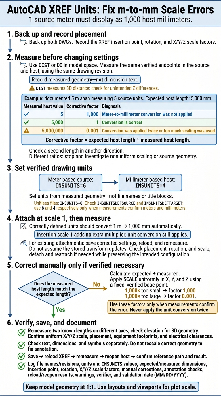
AutoCAD XREF Units: Fix Meter-to-Millimeter Scale Errors
2. Check Scale with a Known Dimension
Measure the Same Feature in Both Drawings
Before changing anything, use a verified length to check whether the XREF is scaled incorrectly. Pick a documented room width, grid spacing, or equipment length with known endpoints. Make sure the source and host drawings use the same revision. For equipment, use the manufacturer’s verified footprint - not a nominal outline or an estimated clearance.
In the source drawing’s model space, run DIST or DI. Use object snaps such as Endpoint, Intersection, Midpoint, or Perpendicular to select the feature’s actual endpoints. Record the measured value, not the dimension text. Then measure between the same physical points in the host drawing. If needed, temporarily attach the XREF to a backup host drawing without changing the source geometry.
Set UNITS precision high enough to show any difference. For flat layouts, check that both points have the same elevation. DIST measures 3D distance, so a stray Z value will affect the result.
Compare Measurements to Find the Scale Error
Corrective factor = expected host length ÷ measured host length.
The diagnostic values below use a documented 5 m span that measures 5 source units; its expected host length is 5,000 mm.
Expected host dimension Measured source value Measured host value Required corrective factor Likely cause 5,000 mm 5 5 1,000 Meter-to-millimeter conversion was not applied 5,000 mm 5 5,000 1 Conversion is correct 5,000 mm 5 5,000,000 0.001 Conversion was applied twice or too much scaling was used
Check a second length in another direction. Matching ratios confirm a uniform scale error. Different ratios point to nonuniform scaling or incorrect source geometry.
If the lengths match but the XREF is offset or rotated, check placement or rotation - not scale. Clipping can also hide geometry. Annotation issues affect text and symbols, not linework.
Use the measured ratio to set the insertion scale in the next step.
sbb-itb-f008923
3. Set Units and Correct XREF Scale
Set Source and Host Insertion Units
Open each DWG and check UNITS or INSUNITS. Set units based on measured geometry, not the file name or title block. Use the measured ratio from the previous check to decide whether AutoCAD can handle the conversion or you need to correct the scale manually.
| Drawing condition | Unit setting | Verification and action |
|---|---|---|
| Meter-based source | INSUNITS=6 |
Confirm that a documented length in meters matches the measured value in the source drawing. |
| Millimeter-based host | INSUNITS=4 |
Confirm that 1 meter measures 1,000 host drawing units. |
| Unspecified units | INSUNITS=0 |
Check INSUNITSDEFSOURCE and INSUNITSDEFTARGET, then verify a known dimension before attaching. |
| Label does not match measured geometry | Relabel the file to match verified geometry. | Measure the actual scale, then correct or rescale the source. Do not rely on metadata alone. |
For unitless files, INSUNITSDEFSOURCE supplies the assumed source units, and INSUNITSDEFTARGET supplies the assumed target units. Use 6 and 4, respectively, only when measurements confirm meters and millimeters. These fallbacks help with legacy files, but setting explicit drawing units is the better choice.
Attach at Scale 1 and Verify Automatic Conversion
Once both drawings have the correct unit definitions, attach the XREF at scale 1. AutoCAD should automatically convert 1 source meter into 1,000 host millimeters. Scale 1 adds no extra multiplier; unit conversion still applies.
For an existing attachment, save a copy of the host drawing first. Correct and save the unit settings, then reload the XREF and remeasure. Don't assume its stored transform updates. Check the insertion point, rotation, and scale values. If needed, detach and reattach it with the corrected units, keeping the intended placement and reference configuration.
Calculate and Apply a Manual Scale Correction
If AutoCAD doesn't convert correctly, calculate the adjustment:
Correction factor = expected host dimension ÷ measured host dimension
Select the XREF, run SCALE, and apply the factor uniformly in X, Y, and Z. Use a fixed base point - usually the project origin or the verified insertion point. Don't add another multiplier if AutoCAD has already converted the units.
| Observed problem | Action |
|---|---|
| Geometry is 1,000 times too small | Apply 1,000 only after confirming the measured error and checking the existing conversion. |
| Geometry is 1,000 times too large | Check for duplicate conversion. Apply 0.001 only after the measured error confirms it. |
After scaling, remeasure the same dimension before moving to annotation checks.
4. Verify Geometry, Annotation, and Saved Settings
Recheck Dimensions and Electrical Layouts
After correcting the scale, check the linework first. Remeasure the original control dimension and a second known dimension on a different axis. Confirm that the X, Y, and Z scale values match. If the reference includes 3D geometry, check an elevation, too. If one direction is correct and another is wrong, stop. Investigate nonuniform scaling or inconsistent source geometry instead of applying another multiplier.
Compare equipment footprints with the specific manufacturer’s dimensions. Review room boundaries, cable routes, panel locations, connection points, door swings, and maintenance access. Check plans alongside elevations, and confirm that equipment identifiers match the single line diagram.
Check Text and Symbols Separately
Once the geometry passes, check text, attributes, dimensions, leaders, and symbols separately in model space and layouts. Review each object’s active annotation scale, annotative status, and assigned scales. Use OBJECTSCALE to change annotative assignments and SCALELISTEDIT to manage the scale list. Do not rescale the XREF to fix annotation.
Set ANNOALLVISIBLE to 1 only when diagnosing missing annotative objects, then restore the required setting. Test the affected layout separately: this setting is saved independently for model space and each layout.
Reload, Reopen, and Document the Result
After checking geometry and annotation, save the host drawing and any source files you changed. Reload the XREF and remeasure the control dimension. Then reopen the host, confirm the result, and check that the reference path resolves.
Record the following in the issue log:
- File names and revisions; source and host units and
INSUNITSvalues; expected and measured control dimensions; insertion point, rotation, X/Y/Z scale factors, and any manual correction. - Annotation results, reload/reopen results, unresolved warnings, the verifier’s name, and the validation date in MM/DD/YYYY format.
Stop Making These AutoCAD Xref Mistakes
5. Conclusion: Verify XREF Units Before Use
After checking the scale, verify a known dimension before using the XREF. Confirm the source units, host units, and intended insertion scale. Attach the XREF at scale 1, then measure a known feature to check that the unit conversion is correct.
Once the control dimension matches, keep model geometry at 1:1. Set the plot scale through layouts and plot settings.
If you use Elora Grid to turn tender inputs into bid and design drawings, check the source units and key dimensions before using the output for coordination.
FAQs
Will changing INSUNITS rescale existing geometry?
No. Changing INSUNITS does not rescale existing geometry. It sets the drawing’s insertion units, which AutoCAD uses to scale incoming blocks and Xrefs - not geometry already in model space.
To fix scale errors, use the Scale command. To prevent them, match the source and host drawing units and check the Xref insertion scale settings before inserting the reference.
How do nested XREFs affect unit conversion?
Nested XREFs can multiply unit-conversion errors. Each reference may use its own source units and insertion scale. If the outer XREF is scaled or read incorrectly, the inner XREFs inherit that scaling. Their dimensions can end up off by a fixed factor - often 10, 100, or 1,000.
Keep the documented source and host units consistent, verify the insertion scale, and check a known dimension before relying on the referenced geometry.
How can I fix XREF scale without shifting its position?
Select the XREF and run the SCALE command. When prompted for a base point, choose a consistent reference point, such as a corner or the insertion point. The XREF resizes around this anchor, keeping that point in place.
Before using the XREF, check the corrected scale. Measure a known dimension and compare it with the original design specifications.