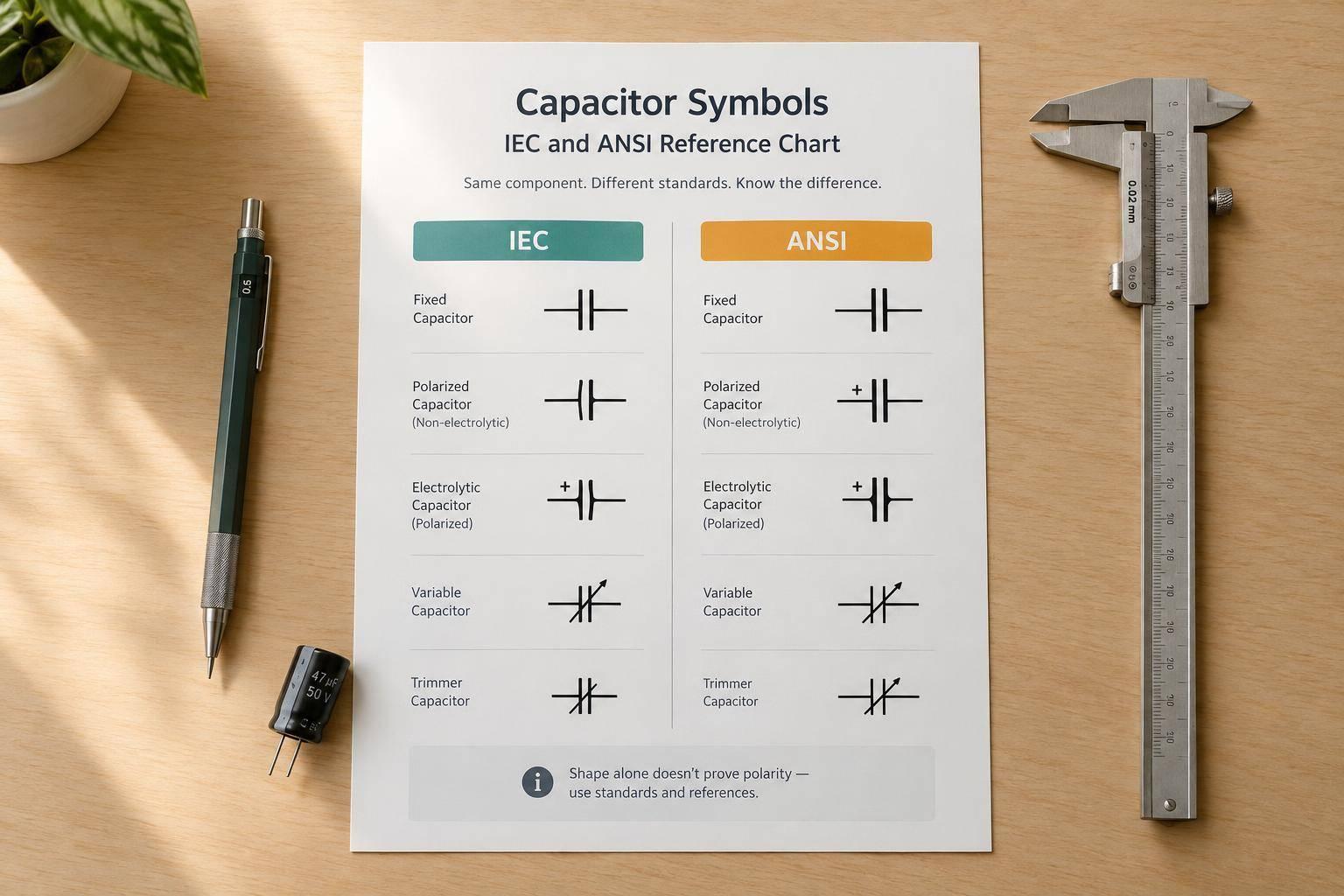
Capacitor Symbols: IEC and ANSI Reference Chart
A capacitor symbol shows connections - not its capacitance, voltage rating, or physical shape. For IEC and ANSI/IEEE drawings, check the project’s required standard, then verify polarity and terminal connections against the manufacturer’s datasheet. This verification is a critical step when reading a single line diagram to ensure the schematic matches the physical installation.
The main checks are simple:
- Symbol form: Two parallel plates commonly indicate a nonpolarized capacitor. A diagonal arrow indicates adjustment, not polarity.
- Polarity: IEC polarized forms commonly use a + mark. ANSI/IEEE polarized forms commonly pair a straight positive plate with a curved negative plate. Shape alone is not enough.
- Drawing agreement: Terminal numbers, PCB footprints, ratings, and BOM entries must match the specified part.
Quick Comparison
| Check | IEC | ANSI/IEEE |
|---|---|---|
| Reference | IEC 60617 | ANSI Y32.2 / IEEE Std 315-1975 |
| Nonpolarized form | Two parallel plates | Two straight plates |
| Common polarized form | Capacitor symbol with + | Straight plate (+), curved plate (−) |
| Adjustable form | Diagonal adjustment indicator | Diagonal arrow |
IEEE Std 315-1975 is listed as Inactive-Reserved, so the required edition matters. If supplier drawings mix conventions or conflict with the datasheet, obtain written clarification before approval.
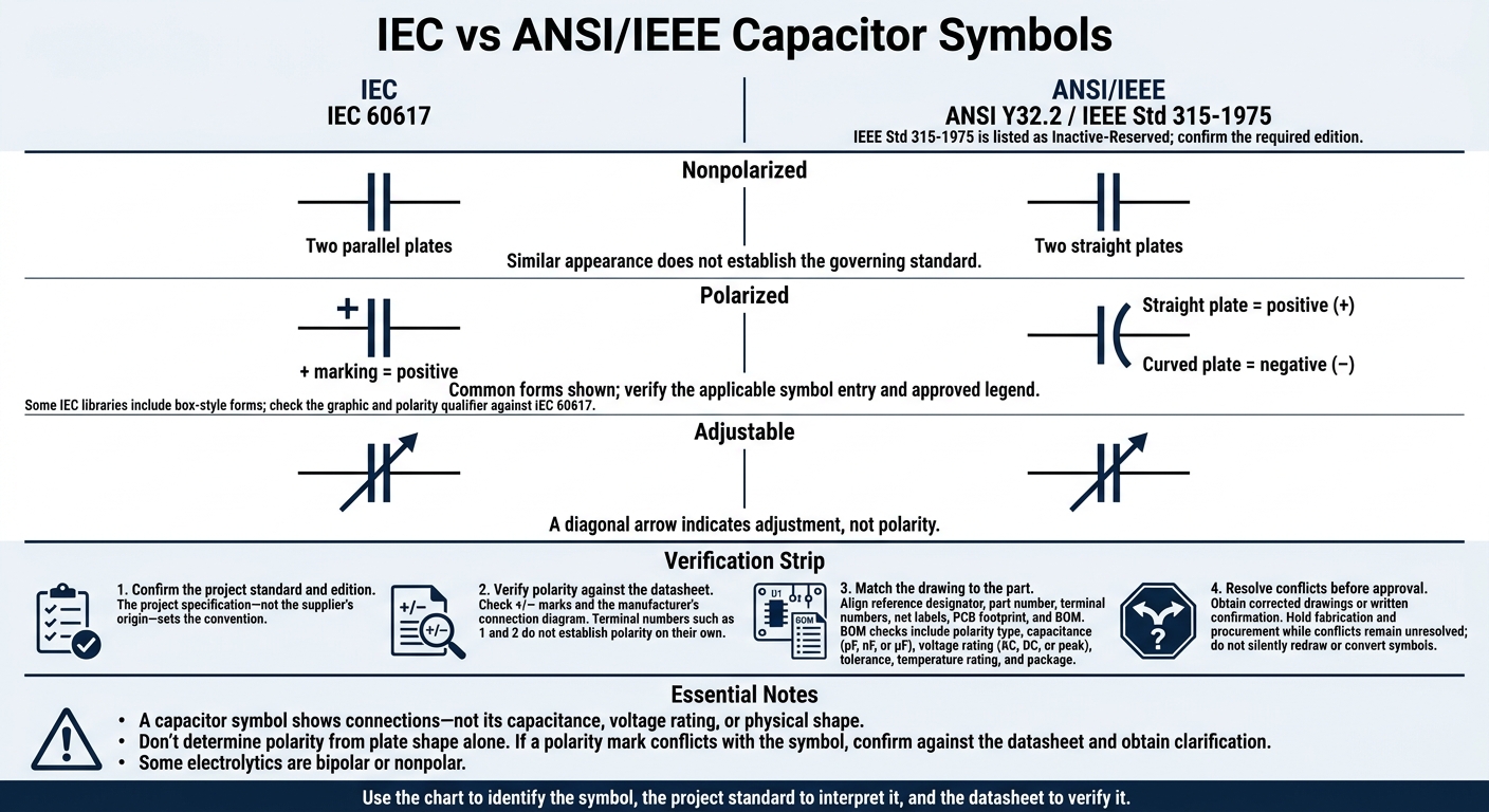
IEC vs ANSI/IEEE Capacitor Symbols
1. IEC Capacitor Symbols
Symbol Forms and References
The IEC general capacitor symbol has two parallel plates and represents non-polarized capacitors, including ceramic, film, and mica types. Some IEC libraries also include a box-style form. Check both the graphic and its polarity qualifier against the IEC 60617 library - don’t assume the shapes are interchangeable. Use this reference form when comparing ANSI/IEEE variants.
An adjustable capacitor adds a diagonal adjustment indicator. Use the variable-capacitor symbol for trimmers and other adjustable parts. The component’s outline alone doesn’t tell you whether it’s adjustable.
Polarity and Terminal Meaning
IEC polarized forms commonly place a “+” beside the positive terminal, sometimes while keeping both plates straight. For a polarized electrolytic capacitor, the positive terminal is the anode, and the negative terminal is the cathode. Connect the positive terminal to the higher potential under the intended operating condition.
Check terminal numbers against the manufacturer’s connection diagram. Include capacitance, tolerance, voltage rating, and technology in the device data or bill of materials. Label capacitance values in pF, nF, or µF, and specify whether the voltage rating is AC, DC, or peak.
Supplier Drawing Consistency
Separate what a symbol means from how it looks. Map unfamiliar supplier symbols to the IEC reference. In a drawing-review cross-reference, record each symbol’s function, polarity convention, and governing reference.
Check reduced-scale PDFs and prints for missing plus signs or faint symbols. If polarity is still unclear, request a corrected drawing or written confirmation - don’t silently redraw the symbol.
sbb-itb-f008923
2. ANSI/IEEE Capacitor Symbols
Symbol Forms and References
The U.S. reference standard is ANSI Y32.2 / IEEE Std 315-1975, Graphic Symbols for Electrical and Electronics Diagrams. It defines the U.S. capacitor forms used in comparisons with IEC drawings. IEEE lists the 1975 edition as Inactive-Reserved, so specify the required edition and drafting convention.
IEC emphasizes international symbol references. ANSI/IEEE uses plate shape to indicate polarity:
- Nonpolarized: two straight plates
- Polarized: a straight plate (+) and a curved plate (−)
- Adjustable: a diagonal arrow
A diagonal arrow indicates adjustability, not polarity. Check the legend and drafting notes. IEC drawings may use different capacitor bodies or plate styles, but the symbol’s function must still match the part.
Polarity and Terminal Meaning
Polarity is the main visual difference between these symbol forms. In ANSI/IEEE polarized symbols, the curved plate marks negative, and the straight plate marks positive. Check the datasheet if an older symbol library makes that distinction unclear.
Terminal numbers such as 1 and 2 do not establish polarity on their own. Verify the symbol, polarity mark, part number, and datasheet together.
Supplier Drawing Consistency
Check the drawing set for reversed polarity, missing adjustment arrows, and inconsistent terminal numbers. Pay particular attention when a vendor package mixes IEC and ANSI symbols. Keep CAD block names separate from standard references: library names are not official IEEE symbols. Complete this symbol check before verifying the plus and minus marks on polarized parts.
Polarized Capacitor Marks and Terminals
Use this checklist when supplier drawings mix IEC and ANSI symbols.
| Review point | IEC-style polarized form | ANSI/IEEE polarized form |
|---|---|---|
| Symbol | Straight-plate or box-style capacitor with a nearby + mark | One straight plate and one curved plate |
| Required callout | + marking = positive | straight plate = positive; curved plate = negative |
| Standard reference | IEC 60617 | ANSI Y32.2 / IEEE Std 315-1975 |
Don’t determine polarity from plate shape alone. Check the +/− mark first. If it conflicts with the symbol, confirm polarity against the datasheet. Some electrolytics are bipolar or nonpolar.
Next, verify the part number and footprint. Match the reference designator and part number to the datasheet. Trace terminal numbers and net labels to the manufacturer’s connection diagram, then check the PCB footprint. The BOM must match the polarity type, capacitance, voltage rating, tolerance, temperature rating, and package. Check any proposed replacement part against these requirements, too.
If the drawing still conflicts with the datasheet, document the issue immediately. Record unresolved conflicts as drawing comments, including the sheet, component reference, affected terminal or net, conflicting evidence, and required correction. Hold fabrication and procurement until corrected drawings or written confirmation arrive.
Check Supplier Drawings Across Standards
Once you’ve checked the symbol form, verify that the supplier followed the project’s governing standard throughout the drawings.
The project specification - not the supplier’s origin - sets the convention. Check the contract, design basis, drafting manual, and approved legend. Record the required standard and edition. If those references are missing or conflict, request clarification.
| Review area | IEC-based check | ANSI/IEEE-based check | Review action |
|---|---|---|---|
| Governing reference | Confirm the applicable IEC 60617 symbol entry. | Confirm the specified IEEE Std 315-1975 or ANSI Y32.2-1975 reference. | Record the contractual requirement. |
| Symbol meaning | Match the function and qualifiers to the applicable IEC 60617 entry. | Match the symbol form to the cited reference and approved legend. | Compare the symbol’s meaning and connections - not just its appearance or CAD block name. |
| Document alignment | Use the approved IEC legend for terminal mapping. | Use the approved ANSI/IEEE legend for terminal mapping. | Check that schematics, single-line diagrams, tags, ratings, and quantities agree across the package, including terminal schedules, BOMs, and datasheets. |
| Exceptions | Identify departures from the approved IEC legend. | Identify unexplained legacy or supplier-specific forms. | Flag mixed conventions, polarity conflicts, missing marks, and unexplained deviations. Resolve them through an approved revision or documented explanation. |
For capacitors that belong to a bank, review the full assembly, not just the capacitor symbol.
If standardization is impractical, keep supplier symbols only with engineering approval and a controlled legend or note. Identify the source and edition, map each retained symbol to its project meaning, and state the terminal and polarity conventions. Apply that note across all affected sheets and retain the source drawings.
Elora Grid can generate schematics and single-line diagrams from tender drawings, but engineering review against the project standard still governs symbol compliance.
Conclusion: Confirm the Standard and Polarity
Nonpolarized capacitor symbols can look similar across IEC 60617 and ANSI/IEEE. Use the chart to identify the symbol, the project standard to interpret it, and the datasheet to verify it. The chart is a first check - not the final authority. Shape alone doesn’t confirm capacitor technology or polarity.
For polarized forms, check what the curved plate or “+” mark means. Then match the schematic to the datasheet and the marked terminals. Always verify terminal polarity.
If the symbol conflicts with the datasheet, get written clarification before approval. Don’t silently convert the symbol. Approve only drawings that match the governing standard and the manufacturer’s polarity data.
FAQs
How do I distinguish trimmer and variable capacitor symbols?
Check the graphic qualifiers in the IEC or ANSI/IEEE standard specified for your project. They identify adjustment features and help you distinguish preset or trim adjustments from controls used during operation.
Confirm the intended adjustment method in the project legend and manufacturer documentation. Vendor block identifiers vary; they aren’t universal standard codes.
How should I show a bipolar electrolytic capacitor?
Use an electrolytic capacitor symbol with the appropriate construction qualifier. Check the graphic against your project legend and the relevant standard, such as IEEE/ANSI 315-1975. Don’t assume a generic capacitor symbol or rotated plate graphic is enough. Clearly state the polarity and voltage ratings in the accompanying annotations to help ensure correct circuit connections.
When is a mixed-standard drawing acceptable?
A drawing can use mixed standards if it meets the project requirements, follows the applicable standards, and uses the approved legend for that deliverable. Different identifiers on the same drawing do not mean they’re universally compatible or can be converted one-to-one.
When reviewing a drawing that uses multiple conventions, check that each symbol is clearly labeled with its source and edition. Use the project-approved legend - don’t assume symbols from different libraries mean the same thing.