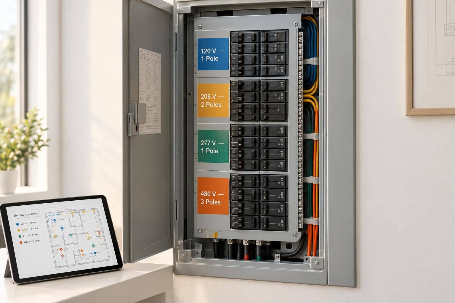
Electrical BIM Connectors: Voltage and Pole Settings
Match the device’s voltage, poles, and system type to the circuit and panel - not just the panel’s voltage label. For example, a 277 V lighting load on a 480Y/277 V panel needs a 277 V, one-pole connector.
In Revit and AutoCAD MEP, the checks are similar, but the settings differ:
- Confirm the equipment rating first. Check voltage, phase, poles, and wire count against project documents and manufacturer data.
- Trace connection errors before changing values. Review existing assignments, connector parameters, panel distribution settings, and breaker space.
- Choose fixed or circuit-driven values with care. Verify inherited values and recheck placed devices after family or style changes.
Keep equipment schedules, panel schedules, and single-line diagrams consistent. A successful software connection does not confirm electrical code compliance or sufficient panel capacity.
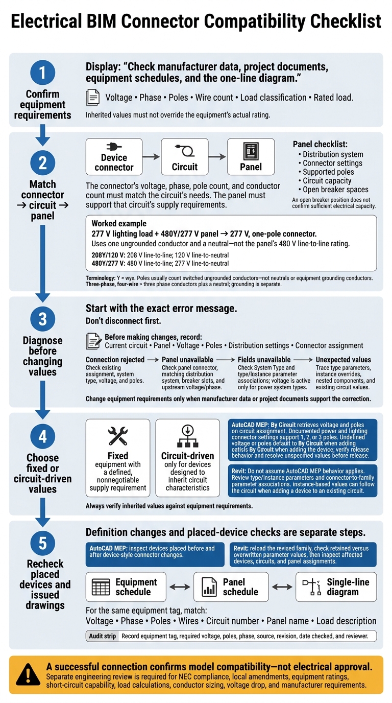
Electrical BIM Connector Compatibility Checklist
How connectors match circuits and panels
Once you’ve set the connector values, check that the panel supports the same electrical requirements. Compatibility runs from connector to circuit to panel. The connector’s voltage, phase, pole count, and conductor count must match the circuit’s needs. The panel, in turn, must support that circuit’s supply requirements. In Revit, voltage and pole mismatches can keep a panel out of the selection list.
Check panel distribution before assigning devices
Check the panel’s distribution configuration first. Then use the equipment schedule, one-line diagram, and manufacturer data to confirm the load’s required voltage, poles, phase, and conductors. Inherited values still need engineering verification. They should never override the equipment’s actual rating.
For a 277 V lighting load on a 480Y/277 V panel, set the connector to 277 V and one pole. Do not use the panel’s 480 V line-to-line rating for that load. The load uses one ungrounded conductor and a neutral.
Read panel voltage, phase, and wire labels
In 208Y/120 V, “Y” identifies a wye system: 208 V is line-to-line, and 120 V is line-to-neutral. 480Y/277 V follows the same pattern. A three-phase panel can supply single-phase loads when the voltage and pole count match.
Keep poles, phases, and wires separate. Pole count usually refers to the ungrounded conductors controlled by a breaker or switch - not neutrals or equipment grounding conductors. Three-phase, four-wire means three phase conductors plus a neutral. Grounding is handled separately.
Imported voltage labels need the same matching checks. For example, Australian documents may show 400/230 V. On imported projects, keep the local voltage, phase, and standard basis intact until the electrical engineer confirms the project standard. When these labels don’t align, the circuit won’t assign cleanly.
sbb-itb-f008923
Why circuit and panel connections fail
The software blocks a connection when the connector and panel settings don’t match. Start with the exact error message: pole, voltage-range, system-type, and distribution-system errors each point to different settings.
Find the cause of a connection failure
Before making changes, record the device’s current circuit, panel, voltage, poles, distribution settings, and connector assignment. Don’t disconnect it first. The existing assignment may hold valid design information.
Use the error message to narrow the problem to the device connector, panel connector, or distribution system.
| Symptom | Likely Cause | Correction |
|---|---|---|
| Device connection is rejected | The connector already has an assignment, uses an incompatible system type, or doesn’t match the circuit’s voltage or poles. | Check the existing assignment and connector properties, then correct the documented mismatch. |
| Panel is unavailable | The panel connector lacks suitable voltage or pole settings, no matching distribution system exists, or suitable breaker slots aren’t available. | Check the panel connector, the distribution system in Electrical Settings, and available slots. Verify upstream voltage and phase settings, too. |
| Voltage or pole fields are unavailable | The connector’s system type or a family parameter controls editing. Voltage is active only for power system types. | Check System Type and type/instance parameter associations before changing the family. |
| Unexpected values appear in the fields | Type parameters, instance overrides, nested components, or existing circuit values control the connector. | Trace the parameter that controls the value. Compare the actual connector properties with the circuit - not just the visible device rating. |
Change equipment requirements only when manufacturer data or project documents support the correction. Remove an assignment only when the documented workflow calls for it, then check the reassignment against the circuit and panel data.
A successful connection confirms model compatibility - not electrical approval. NEC compliance, local amendments, equipment ratings, short-circuit capability, load calculations, conductor sizing, voltage drop, and manufacturer requirements still need separate engineering review.
When to use fixed or circuit-driven values
Once a connector can match the panel, decide whether its voltage and pole values should stay fixed or follow the circuit. Use fixed values when the equipment rating is nonnegotiable. Use circuit-driven values only when the device is designed to inherit them. Fixed values preserve the equipment requirement; circuit-driven values follow the supply defined by the circuit and panel.
Record the equipment tag, required voltage, poles, phase, source, revision, date checked, and reviewer. This choice controls how the placed device behaves during assignment and revision.
Use By Circuit and Undefined only where supported
In AutoCAD MEP, By Circuit retrieves voltage and pole values when you assign the circuit. The documented power and lighting connector settings support 1, 2, or 3 poles. Check inherited values against the equipment requirement.
| Setting | Intended Use | Verification Required |
|---|---|---|
| Fixed | Equipment with a defined supply requirement | Check manufacturer data, equipment schedules, and the intended circuit. |
| By Circuit | Devices designed to inherit circuit characteristics | Confirm the assigned panel, distribution system, voltage, and poles. |
| Undefined | Temporary or unspecified value | Check how the software release handles the setting, then resolve the value before releasing the drawing. |
AutoCAD MEP documents that Undefined voltage or poles default to By Circuit when you add the device. Check the placed device because behavior can vary by software release.
Do not apply this AutoCAD MEP behavior to Revit. In Revit, distribution-system values come from type or instance parameters. Instance-based values can follow the circuit when you add a device to an existing circuit.
Recheck placed devices after definition changes
Changing an AutoCAD MEP device-style connector does not guarantee that existing devices receive the revised settings. Check devices placed both before and after the change, including their actual voltage, poles, and inherited values. Treat definition changes and placed-device checks as separate steps.
For Revit, reload the revised family and check whether the reload retains or overwrites existing parameter values. Review connector-to-family parameter associations and confirm whether each controlling parameter is type- or instance-based. Then inspect affected placed devices and recheck their circuits and panel assignments. Reloading alone does not confirm that those assignments are correct. Use the verified values to check supply requirements before assigning the circuit.
What to check before assigning a circuit
After troubleshooting mismatches, verify the supply data before assigning the circuit. Compare the equipment’s load classification and rated load with the target circuit. Then check voltage, poles, phase, and wire count.
Identify which parameter level controls the connector values before assigning the circuit. If checking those values does not resolve the assignment issue, move to the panel-side checks.
If the panel still will not assign, check its distribution system, connector settings, supported poles, circuit capacity, and open breaker spaces before issuing drawings. An open breaker position does not confirm sufficient electrical capacity.
Keep supply requirements consistent across drawings
Confirm that the supply data matches across every issued drawing. For the same equipment tag, compare the equipment schedule, panel schedule, and single-line diagram. Voltage, phase, poles, wires, circuit number, panel name, and load description must all match.
FAQs
How do I model equipment with multiple voltage ratings?
Record each voltage rating on its own line in the equipment schedule or device properties. Ratings aren’t interchangeable: each voltage and pole configuration must match the project one-line diagram and specifications.
Update ratings and connection points in the authoritative 2D source drawings before updating 3D models. If values conflict, check the governing design document, document the discrepancy, and resolve it before moving forward.
Why is my panel unavailable when the voltage matches?
A panel may remain unavailable even when the voltage matches. Other electrical ratings and parameters must match, too. Check phase, frequency, grounding, and source configuration across your documents.
Bus ratings, interrupting ratings, and wire systems can also cause mismatches. Make sure circuit topology, protective device ratings, and terminal connection points agree across your schematic and single-line diagrams.
How can I find what controls my connector settings?
Connector settings come from the device properties and parts list linked to your equipment ID. Update circuit logic and ratings in your 2D schematic or single-line diagram, which serves as the source of truth for your electrical topology. Then align the mapped properties in your 3D models to avoid mismatches.
Check equipment registers and connection data to confirm that voltage, phase, and connection arrangements match across project documents.