ISO 5457: Electrical Drawing Borders and Margins
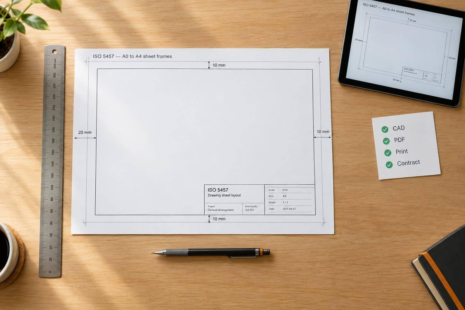
ISO 5457 sets the sheet-layout rules for technical drawings: a 20 mm left filing border, 10 mm borders on the other sides, and a continuous frame. Use millimeters and the standard edition named in the contract - not inch-based substitutes.
For electrical drawing sets, that means using approved A0–A4 templates, placing title blocks and reference marks correctly, and checking CAD-generated sheets, exported PDFs, and printed output. U.S. projects also need a contract check: ISO and ANSI/ASME formats are not interchangeable.
A correct layout does not confirm a safe electrical design. Circuit logic, equipment ratings, protection, and cable sizing still need separate engineering approval.
AutoCAD - Rahmen erstellen nach DIN EN ISO 5457 & DIN 824 - Tipp #3
sbb-itb-f008923
ISO Sheet Sizes, Borders, and Drawing Space
ISO 5457 Sheet Sizes, Borders and Drawing Space
A0–A4 Sheet Sizes and Orientation
Use millimeters as the controlling units.
| ISO size | Orientation | Trimmed width × height (mm) | Usable framed drawing space (mm) | Electrical application |
|---|---|---|---|---|
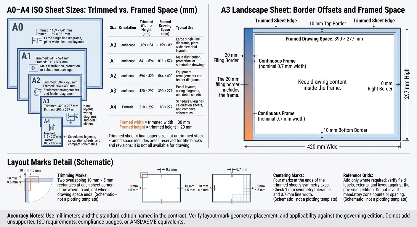
| A0 | Landscape | 1,189 × 841 | 1,159 × 821 | Large single-line diagrams, plant-wide electrical layouts |
| A1 | Landscape | 841 × 594 | 811 × 574 | Main distribution, protection, or substation drawings |
| A2 | Landscape | 594 × 420 | 564 × 400 | Equipment arrangements and feeder diagrams |
| A3 | Landscape | 420 × 297 | 390 × 277 | Panel layouts, wiring diagrams, and detail sheets |
| A4 | Portrait | 210 × 297 | 180 × 277 | Schedules, legends, calculation sheets, and compact schematics |
The trimmed sheet is the final paper size - not the larger, untrimmed stock sheet. To calculate the framed area, subtract 30 mm from the width and 20 mm from the height. Part of that area must hold title blocks and revisions, so it isn't all available for drawing.
With the sheet size set, use the border offsets to define the drawing field.
20 mm Filing Border, 10 mm Borders, and Frame
Measure every offset from the trimmed edge. The 20 mm left filing border includes the frame. For reference, 20 mm is about 0.79 in., and 10 mm is about 0.39 in. Keep the metric values in your template.
| Layout requirement | Template implementation | Review check |
|---|---|---|
| 20 mm left filing border | Set the filing-edge offset to 20 mm | Measure from the trimmed left edge |
| 10 mm top, right, and bottom borders | Set each offset separately | Verify all three distances |
| Continuous frame, nominal 0.7 mm line width | Use a locked border layer | Check continuity and plotted line weight |
| Content inside the frame | Add a non-plotting safe-area guide | Flag text, dimensions, conductors, and leaders that cross the frame |
Trimming Marks, Centering Marks, and Reference Grids
Once the frame is set, add trimming and centering marks separately.
Trimming marks show where to cut - not where the drawing space ends. Each mark uses two overlapping 10 mm × 5 mm rectangles at the sheet corners. Keep these marks separate from the continuous frame, and check their geometry, placement, and applicability against the governing edition.
Place the four centering marks at the ends of the trimmed sheet’s symmetry axes. Check the 1 mm symmetry tolerance and 0.7 mm line width. Add reference grids only where required, and check their field labels, extents, and layout against the governing edition.
Build Controlled Electrical Drawing Templates
Use a separate approved template for each sheet size and title-block variant. Don’t scale one border block across formats. For each master template, record the governing standard, project CAD manual, intended print size, filing method, owner, version, approval date, and change log.
After approval, place title blocks, revision space, and zone references without changing the frame geometry.
Place Title Blocks, Revision Areas, and Zone References
Keep three controls separate: ISO 5457 covers sheet layout, ISO 7200 covers title-block data, and project rules govern document control. ISO 7200 defines field names, contents, and lengths. Document each required field, its allowed values, and its owner. Don’t assign scale, units, approval, revision, or issue-status fields to ISO 5457.
| Element | Placement and template control |
|---|---|
| Frame | Protect the approved drawing-space boundary from accidental edits. |
| Filing margin | Reserve the left-side filing area and keep project content out. |
| Title block | Place at the bottom-right of the drawing space for A0–A3; use the lower short side for A4. |
| Revision area | Place within or beside the title-block system, allowing room for the expected issue history. |
| Drawing content | Keep views, notes, schedules, and dimensions clear of reserved document-control areas. |
| Zones | Use consistent row-and-column references around the frame. |
Check US Sheet Formats and Contract Requirements
For U.S. projects, check the contract’s format rules before finalizing the template.
ANSI/ASME formats and ISO A-series layouts aren’t interchangeable. ASME Y14.1 defines decimal-inch sheet sizes and formats for engineering drawings. Dimensions, printable areas, border conventions, title-block proportions, and plotting settings may differ.
Before approval, record the contract’s required standard and edition, units, scales, title-block rules, approval workflow, and PDF naming requirements. Meeting ISO sheet-layout requirements alone doesn’t establish U.S. contractual compliance.
Set Up CAD Templates and Verify Generated Outputs
Build each paper-space layout around the approved geometry. In page setup, set the paper size, viewport scale, annotation scale, text style, dimension style, line weight, fonts, and PDF settings.
Keep construction guides on a nonprinting template layer, while preserving the required visible frame and marks in every output. Test a populated drawing before release, then repeat the test after CAD or plotter updates.
Generated drawings need the same template checks as manually drafted sheets.
Elora Grid can generate 2D and 3D general arrangements, single-line diagrams, and schematics from uploaded tender drawings and related documents. Place the output into the approved template. Before issue, verify units, viewport scales, zone references, clearances, and exported PDF sheet geometry - generation does not equal compliance.
Review Generated Sheets Before Issue
Check Sheet Geometry and Content Placement
Compare every page with the approved template. Mark Pass only after checking the final output. For each failure, assign a reviewer and record the root cause: template, content placement, or export settings.
Apply this checklist to the full exported set before issue.
| Check | Acceptance criterion | Result | Corrective action |
|---|---|---|---|
| Sheet geometry | Designation, orientation, trimmed size, and drawing-space dimensions match the approved template | Pass/Fail | Correct the sheet assignment or page setup |
| Borders and frame | Left border is 20 mm; other borders are 10 mm; frame is continuous and 0.7 mm wide. | Pass/Fail | Restore approved frame and border geometry and plot settings |
| Layout marks | Applicable centering, trimming, and reference grid marks are visible and aligned; centering marks meet the 1 mm symmetry tolerance. | Pass/Fail | Restore marks or record an approved exception |
| Document control | Title block, revision, approval, issue-status, sheet-number, and total-count fields match the transmittal | Pass/Fail | Correct fields and regenerate affected sheets |
| Content and zones | No unintended clipping or border intrusion; continuation references match valid sheets and visible zones | Pass/Fail | Reposition content and repair cross-references |
| PDF integrity | Page dimensions, orientation, order, and template revision match the approved set; fonts, symbols, and line weights are retained | Pass/Fail | Correct export settings and regenerate |
| Printed output | Intended scale is retained; frame, title block, annotations, equipment ratings, cable identifiers, terminal numbers, and protective-device settings remain readable | Pass/Fail | Correct print settings or revise the sheet |
| Engineering approval | Circuit logic, ratings, clearances, symbols, and project requirements pass a separate technical review | Pass/Fail | Return to the responsible electrical engineer |
Centering, trimming, and reference-grid marks are layout features, not defects. Flag only unintended frame crossings.
PDF and print checks can catch scaling and output errors that the checklist alone may miss.
Check PDF Dimensions and Printed Sheets
After the checklist passes, verify the PDF and printed output.
Before printing, confirm the exported PDF’s page dimensions. An A3 sheet must measure 297 × 420 mm, with width and height matching its orientation. Check every page for clipped borders, missing title-block fields, substituted symbols, and unreadable annotations. Also confirm that the exported set uses the approved template revision.
When scale must be retained, print one representative sheet for each size and plotter workflow at 100% (“Actual size”). Disable unintended fit-to-page scaling. Document any approved reduction and check that the sheet remains readable at that size.
Conclusion: Use Approved Templates and Verify Final Sheets
Use approved, size-specific templates to control sheet size, orientation, borders, frames, title blocks, and zone references. For traceability, include an owner, revision identifier, and approval date in month/day/year format.
Once template control is complete, freeze the issue record. Keep the release checklist as a project record, including the drawing number, revision, template ID, sheet size, PDF and print checks, reviewers, dates, and approval status. Release the set only when the record is complete.
Layout approval does not equal electrical-design approval. Before release, verify circuit intent, load calculations, fault levels, protection grading, earthing, and cable sizing.
FAQs
How do I resolve conflicting ISO and project layout requirements?
Classify the discrepancy, then record its primary and secondary effects and impact level. Use the project’s order-of-precedence clause to determine which requirement takes priority. If the conflict remains unresolved, request clarification and cite the specific drawing, detail, schedule row, and specification clause.
When 2D and 3D values conflict, use the designated owner’s data - typically 2D for circuit logic and 3D for placement and geometry. Document why you rejected the other value.
Can I reduce an A1 drawing to A3 for review?
Yes, as long as the reduced sheet stays readable and includes all required information. Check that text, annotations, line weights, and critical dimensions are still clear.
Review the exported files, not just the authoring model. Make sure scaling hasn’t clipped, hidden, or broken any details and that all references remain intact.
How can I automate border checks on generated drawings?
Compare generated sheets with your project’s drawing index, and check title blocks against the master transmittal or addendum package. Verify project numbers, sheet titles, revision identifiers, issue status, and dates in MM/DD/YYYY format.
Flag duplicate sheet numbers and missing references, labels, or zones. Log each finding in a discrepancy register and link it to its source file. Before finalizing the bid set, get manual verification and any required engineering approval.