Control GA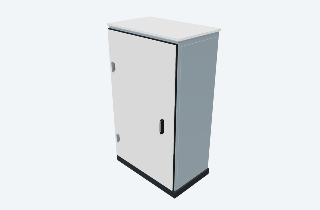
Control / marshalling cabinet
A generic cabinet organising control equipment, terminals and field interfaces.
General arrangement objects
In plain English
A synchronising controller helps generators connect to an AC system and share the load. It checks and adjusts their electrical output before a permitted connection.
In a microgrid with two generators, the controllers help bring the second generator onto the common supply and divide the demand between them.
Use the selected manufacturer's drawings to check the equipment's size, mounting points and cable connections. The layout helps you plan where it fits and how it can be reached for maintenance. An illustrative 3D preview does not establish product dimensions or required clearances.
Read the source: DSE8610 MKII synchronising controller: official source
An original 3D illustration of this equipment type. Rotate and zoom to explore its shape. It does not represent an exact manufacturer model or dimensional layout.

Drag to rotate · Scroll or pinch to zoom · Original educational visualisation. Relative proportions; use the selected manufacturer drawing for dimensions.
Position the controller to support operator visibility and traceable routing to synchronising, generator sensing and control interfaces. Keep network routes identifiable between generator panels.
The linked CAD resource is an electrical wiring reference. Use the separate manufacturer installation drawing for physical dimensions; this original unitless GA illustration is not a fabrication template.
The GA identifies a controller location; it is not a synchronising scheme, protection study or approved switching logic.
These public references support the explanation and provide further detail. Their graphics and downloadable files remain with their publishers.
Official identity and available drawing scope; coordination guidance is independently written.
Elora Grid helps electrical teams work with drawings, specifications and equipment information. Explore the drafting workflow or join the early-access waitlist.