Terminal strip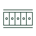
Terminal strip assembly
A physical assembly of identified terminals and the selected connecting accessories.
GA objects
A generic cabinet organising control equipment, terminals and field interfaces.
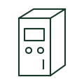
A control or marshalling cabinet houses the components and interfaces defined by its scope. A GA can show the equipment envelope, mounting surfaces, operator devices and cable interfaces. An internal layout links those objects to the schematic and wiring schedules.
The original envelope illustration is unscaled and has no manufacturer dimensions. Follow the cited public resources to the exact product, then use its current drawing and installation information for engineering work.
A cabinet outline is not an internal wiring diagram. Enclosure properties and equipment ratings require the selected product information.
These public references support the explanation and provide further detail. Their graphics and downloadable files remain with their publishers.
Public enclosure construction and installation features.
Public enclosure mounting-surface references.
This illustration was authored independently by Elora Grid to explain the concept. It is not reproduced from a customer drawing, an official standard graphic or a manufacturer CAD file. Its correspondence to an exact IEC or IEEE symbol identifier has not been certified.
SVG and DXF downloads contain this original artwork. DXF uses unscaled drawing units; a GA envelope supplies no product dimensions, clearances or fabrication information. Original artwork is available under CC BY 4.0. Third-party references retain their own terms.
A physical assembly of identified terminals and the selected connecting accessories.
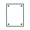
An enclosure mounting surface supporting the selected internal components.
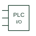
A controller interface point connecting field signals to an identified module channel.
Elora Grid helps electrical teams work with drawings, specifications and equipment information. Explore the drafting workflow or join the early-access waitlist.