HF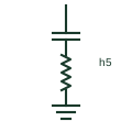
Single-tuned harmonic filter
A shunt series-LC branch tuned near one harmonic order to sink that harmonic current from the network.
SLD / Schematic
A shunt converter that measures load harmonics and injects opposing currents to cancel them at the connection point.
In plain English
An active harmonic filter is a shunt-connected voltage-source converter that measures load current through current transformers, calculates the harmonic content and injects equal and opposite currents. It can also correct power factor and balance load between phases. Response adapts to changing loads, so it does not need tuning to particular orders.
Single-line diagrams show a converter block with a wave or harmonic mark, connected to the switchboard bus through a breaker, with current transformers on the load side or on the supply side depending on the control method. Several modules are often paralleled.
The filter rating is in amperes of compensation current, not in kvar, and it can only cancel harmonics within that current and frequency range. The symbol does not tell you where the current transformers are, which decides whether the filter compensates the whole board or one load.
A shunt converter that measures load harmonics and injects opposing currents to cancel them at the connection point. An active filter cancels harmonics with a converter; a passive filter sinks them with tuned capacitors and reactors.
Read the source: STATCOM: converter-based reactive power compensation · IEC graphical symbols for diagrams
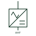
An active harmonic filter is a shunt-connected voltage-source converter that measures load current through current transformers, calculates the harmonic content and injects equal and opposite currents. It can also correct power factor and balance load between phases. Response adapts to changing loads, so it does not need tuning to particular orders.
Single-line diagrams show a converter block with a wave or harmonic mark, connected to the switchboard bus through a breaker, with current transformers on the load side or on the supply side depending on the control method. Several modules are often paralleled.
The filter rating is in amperes of compensation current, not in kvar, and it can only cancel harmonics within that current and frequency range. The symbol does not tell you where the current transformers are, which decides whether the filter compensates the whole board or one load.
An active filter cancels harmonics with a converter; a passive filter sinks them with tuned capacitors and reactors.
These public references support the explanation and provide further detail. Their graphics and downloadable files remain with their publishers.
Public converter-based compensator page noting active filtering capability.
IEC graphical symbol context for converters.
This illustration was authored independently by Elora Grid to explain the concept. It is not reproduced from a customer drawing, an official standard graphic or a manufacturer CAD file. Its correspondence to an exact IEC or IEEE symbol identifier has not been certified.
SVG and DXF downloads contain this original artwork. DXF uses unscaled drawing units; a GA envelope supplies no product dimensions, clearances or fabrication information. Original artwork is available under CC BY 4.0. Third-party references retain their own terms.
A shunt series-LC branch tuned near one harmonic order to sink that harmonic current from the network.
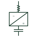
A voltage-source converter in shunt that injects or absorbs reactive current to support voltage, independent of system voltage.
An active harmonic filter uses controlled power electronics for its specified compensation functions.
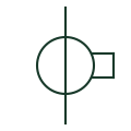
A current-measurement transformer used with metering and protection equipment.
Elora Grid helps electrical teams work with drawings, specifications and equipment information. Explore the drafting workflow or join the early-access waitlist.